Advertisement
INTRODUCTION
The JCM900 4100 was first made in 1990 in response to the perennial problem of 'not enough gain'. At the time, guitarists were hot-rodding their Marshall amps to achieve higher levels of gain, which was expensive and far from reliable. And so Marshall set to work on a remedy. Designing an amplifier with masses of gain is relatively straight forward. The art is to make a high gain amplifier that is not excessively noisy, is reliable and retains great tone. After a period of extended R&D, Marshall provided the world with the answer: the JCM900 Series. "Shredders of the world, please note: The JCM900 saves you the trouble of having your amp hot-rodded. "
-Guitar Player Magazine, 1991.
OVERVIEW
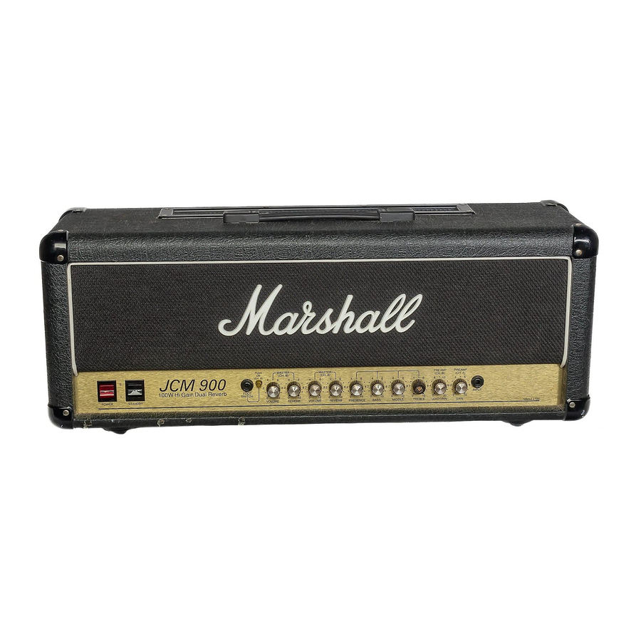
The British made, all-valve 4100 is not only designed to be high gain, it is designed to be versatile, with two independently controlled footswitchable channels, each with its own distinct voicing, Master Volume and footswitchable Reverb. Channel A is voiced for brilliant clean tones when the Gain control is set lower. Turn up the Gain for crunch and more driven tones. Channel B is boosted with enough Gain for fearsome lead tones, ranging from classic lead on lower settings to screaming shred on maximum. The 100 Watt 4100 uses four high quality 5881 output valves for their unique harmonic distortion properties, as well as two ECC83 valves in the preamp. With most valve amplifiers, particularly Marshalls, the best sounds are achieved when, along with the preamp Gain cranked, the Master Volume is set high enough to overdrive the output valves.
It is the delicate working balance between the preamp and the power stage of the amplifier, and the interaction between the EQ controls, that will determine the sonic character produced by the 4100 – experiment to find your sound. Thank you for choosing Marshall and we sincerely hope that your JCM900 4100 Hi Gain Dual Reverb amplifier will provide you with countless hours of 'hotrodded' tone.
FOLLOW ALL INSTRUCTIONS AND HEED ALL WARNINGS KEEP THESE INSTRUCTIONS
IMPORTANT SAFETY INSTRUCTIONS

Before going any further, make sure that your amplifier is compatible with your electricity supply. If you have any doubt, please seek help from a qualified technician – your Marshall dealer can help you in this respect.
MAINS INPUT & FUSE:
Your amplifier is provided with a detachable mains (power) lead which should be connected to the Mains Input socket on the rear panel of the amplifier.
The specific mains input voltage rating that your amplifier has been manufactured for is indicated on the rear panel of the amplifier.
The correct value and type of mains fuse is specified on the rear panel of the amplifier.
NEVER attempt to bypass the fuse or fit one of the incorrect value or type.
TRANSPORTING YOUR EQUIPMENT:
Please ensure that your amplifier is switched off, unplugged from the mains electricity supply and all removable cables have been disconnected from your equipment before attempting to move it.
IMPORTANT SET UP INFORMATION:
- Make sure that the speaker cabinet(s) impedance matches that of the amplifier. See IMPEDANCE SELECT in this manual (Rear Panel Functions #6). Always use a proper speaker cable. Never use a screened (shielded) guitar cable for this purpose.
NOTE: Before connecting or disconnecting the speaker cabinet(s) you MUST switch the amplifier off and disconnect it from the mains electricity supply. Switching on without a speaker plugged in will damage the amplifier. - Ensure that the VOLUME controls on the front panel are set to zero.
- Connect the supplied mains (power) lead into the MAINS INPUT on the rear panel first and then into the mains electricity supply. (Rear Panel Functions #13)
- Plug your guitar into the INPUT jack socket on the front panel.
- Turn the front panel POWER on (Front Panel Functions #15) and wait for a few minutes before going to point 6 below,
- After waiting, engage the STANDBY switch (Front Panel Functions #14).
- Turn the VOLUME controls up to your preferred level and your amp is ready to play.
FRONT PANEL FUNCTIONS


- INPUT
Connects the instrument to the amplifier. (Use a high quality screened lead). - CHANNEL A PREAMP GAIN
Sets the GAIN level for CHANNEL A. Lower settings for clean sounds, higher settings for medium drive and crunch. - CHANNEL B LEAD GAIN
Sets the GAIN level for the boosted CHANNEL B. Lower settings for more classic lead tones, higher settings for maximum drive and sustain. - 5, 6, & 7. TREBLE, MIDDLE, BASS & PRESENCE
Passive rotary EQ circuit. The interactive controls provide a wide range of tonal variation for both channels.
- CHANNEL A REVERB
Controls the amount of REVERB on CHANNEL A.
- CHANNEL A MASTER VOLUME
Controls the overall VOLUME level of CHANNEL A. - CHANNEL B REVERB
Controls the amount of REVERB on CHANNEL B. - CHANNEL B MASTER VOLUME
Controls the overall VOLUME level of CHANNEL B. - CHANNEL B 'ON' PUSH SWITCH/LED
Indicates red when CHANNEL B is selected either manually or by remote footswitch. - FOOTSWITCH
Connects the remote dual footswitch for Channel A/B switching and Reverb On/ Off (part # PEDL-91004). - STANDBY SWITCH
This switch is used in conjunction with the mains POWER switch (item #15) to 'warm up' the amplifier before use and to prolong the life of the output valves. When powering up the amplifier always engage the mains POWER switch first (1), leaving the STANDBY switch to the STANDBY position (0). This allows the application of the voltage required to heat the valves to their correct operating temperature. After approximately two minutes the valves will have reached the correct operating temperature and the STANDBY switch can be engaged (1). In order to prolong valve life, the STANDBY switch alone should be used to turn the amplifier on and off during breaks in performance. - POWER
This is the on/off switch for the mains power to the amplifier. When it is switched on (1), the switch will light red. Please ensure that the amplifier is switched off (0) and unplugged from the mains electricity supply before being moved.
REAR PANEL FUNCTIONS


- LOOP LEVEL
Adjusts the level of the FX Loop from -10dBV to +4dBu. Higher settings match modern FX processors and lower settings match floor FX pedals. NOTE: Some FX such as Distortion and Compressor are best suited to connection via the front panel INPUT jack socket. - SEND
Connect to the input of an external FX. - RETURN
Connect to the output of an external FX. - RECORDING COMPENSATED LINE OUTPUT
Use this jack socket for direct connection to recording equipment or PA system. The signal is specially filtered for optimum recording performance. - DIRECT LINE OUTPUT
Unfiltered preamp signal for connection to an external power amplifier. NOTE: Using the DIRECT LINE OUTPUT does not omit the need for a speaker load to be connected to the 4100 output stage. See item #1 in Important Setup Information in this manual.
- IMPEDANCE SELECTOR
Two-way switch for matching amplifier and speaker impedance. - LOUDSPEAKERS
Parallel wired jack sockets for connecting speaker cabinet(s). Ensure that the speaker cabinet(s) is easily capable of handling the full amplifier power and that the impedance is correctly selected (item #6). If in any doubt, consult your Marshall dealer for advice. - MODE
Switches the amplifier from HIGH to LOW power output. The LOW setting configures the output stage to 'triode' operation which halves the rated output. The HIGH power position configures the amplifier to 'pentode' operation for full 100 Watt rated power output. NOTE: Switching to lower power will not half the volume of the amplifier. The purpose of this feature is to alter the amplifier's tonal character and playing feel. - & 10. VALVE FAILURE LED (OPV1 – 4)
VALVE FUSE (OPV1 – 4)
In the case of output valve failure the fuse (item # 10) will operate, illuminating the FAIL LED (item # 9). This fuse applies to output valves 1 & 4. The amplifier will continue to function on reduced power – valves 2 & 3 only. In this event service should be obtained as soon as possible to prevent premature aging of output valves 2 & 3.
- & 12. VALVE FAILURE LED (OPV2 – 3)
VALVE FUSE (OPV2 – 3)
Similar functions to items #9 & #10 above, but applying to output valves 2 & 3.
- MAINS INPUT
Connects the amplifier to the mains power supply. NOTE: Always ensure that the incoming mains voltage matches that of the amplifier. If in doubt consult your Marshall dealer. - MAINS POWER FUSE
Protects the amplifier and mains supply in the event of a fault. NOTE: Always ensure that the fuse value matches the labelling on the amplifier rear panel. If in doubt consult your Marshall dealer.

Documents / ResourcesDownload manual
Here you can download full pdf version of manual, it may contain additional safety instructions, warranty information, FCC rules, etc.
Advertisement


Need help?
Do you have a question about the JCM 900 4100 and is the answer not in the manual?
Questions and answers