Table of Contents
Advertisement
Quick Links
Advertisement
Table of Contents

Related Manuals for Linx Technologies 250 Series


Summary of Contents for Linx Technologies 250 Series
- Page 1 250 Series Master Development System User's Guide...
- Page 2 Warning: Linx radio frequency ("RF") products may be used to control machinery or devices remotely, including machinery or devices that can cause death, bodily injuries, and/or property damage if improperly or inadvertently triggered, particularly in industrial settings or other applications implicating life-safety concerns. No Linx Technologies product is intended for use in any application without redundancies where the safety of life or property is at risk.
-
Page 3: Table Of Contents
Introduction Ordering Information 250 Series Transceiver Development Board 250 Series Transceiver Evaluation Module Using the Development Boards Using the Development Boards Troubleshooting The Prototyping Area Range Testing Master Development Software About Antennas In Closing 250 Series Master Development Board Schematic... -
Page 5: Introduction
Figure 1: 250 Series Master Development System Introduction The Linx 250 Series RF modules offer a simple, efficient and cost-effective method of adding wireless communication capabilities to any product. The Master Development System gives a designer all the tools necessary to correctly and legally incorporate the 250 Series into an end product. -
Page 6: Ordering Information
Part Number Description MDEV-915-250 250 Series Master Development System Figure 2: Ordering Information 250 Series Transceiver Development Board Figure 3: 250 Series Transceiver Development Board 1. Prototyping Area 7. RS-232 Connector 2. Batteries (3xAAA) 8. RS-232 Jumpers 3. On-Off Switch 9. -
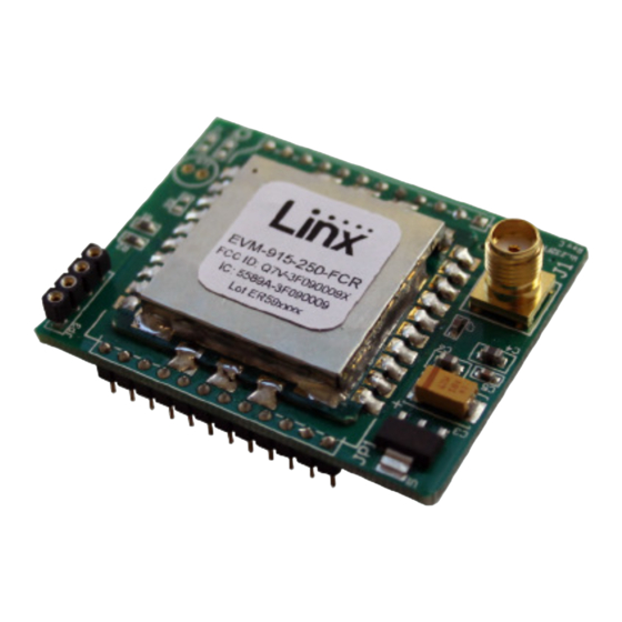
Page 7: 250 Series Transceiver Evaluation Module
250 Series Transceiver Evaluation Module Figure 4: 250 Series Transceiver Evaluation Module Using the Development Boards The development system provides a stable platform to test and evaluate the performance of the modules. Everything required for basic testing is included in the box. - Page 8 (Figure 5). Make sure it is seated fully and correctly. Figure 5: 250 Series Transceiver Evaluation Module on the Development Board 2. Screw an antenna onto each EVM board and install the AAA batteries. 3. Set the jumpers on the development boards. If using the USB interface then populate the USB jumpers and remove the RS-232 jumpers (Figure 6 A).
- Page 9 Figure 6: 250 Series Development Board Jumpers; (A) for USB Interface; (B) for RS-232 Interface 5. Insert the CD that is included with the kit into the computer and install the Windows software. If already installed, skip this step. 6. Run the software, select “Wi.232FHSS-250” and click “OK” (Figure 7 A).
- Page 10 7. The software opens on the Volatile Registers tab. Click on the “Wireless Chat” tab as shown in Figure 8. Figure 8: 250 Series Transceiver Development System Software Volatile Registers Tab This opens the wireless chat window (Figure 9). –...
- Page 11 Figure 9: 250 Series Transceiver Development System Software Wireless Chat Tab 8. The second board can be connected to the same computer for bench top testing or to a second computer for range testing. Open a second instance of the software if using one computer. If two computers are used then repeat steps 4 through 7 for the second board on the second computer.
- Page 12 9. Power-On both development boards, verifying that the version / copyright information is displayed on the screen from both modules (Figure 10). Figure 10: 250 Series Transceiver Development System Software Wireless Chat Tab with Module Information – –...
- Page 13 10. Type a message into the bottom box in one of the windows. Figure 11: 250 Series Transceiver Development System Software Wireless Chat Tab – –...
- Page 14 11. Press Enter and look for the message to appear in the top box of the window connected to the second module (B). It appears in the middle box of the window for the sending module (A). Figure 12: 250 Series Transceiver Development System Software Wireless Chat Tab; (A) Sent; (B) Received – –...
- Page 15 12. Chat back and forth between evaluation boards, verifying that serial and RF communications are successful. Figure 13: 250 Series Development System Software Wireless Chat Tab; Response (A) Received; (B) Sent – –...
-
Page 16: Troubleshooting
Troubleshooting If the boards fail to work out of the box, then try the following: • Check the batteries to make sure they are not dead. • Make sure that the antennas are connected. • Make sure that the jumpers are set correctly. •... -
Page 17: The Prototyping Area
The Prototyping Area In addition to their evaluation functions, the boards may also be used for actual product development. They feature a prototyping area for the addition of application-specific circuitry. The prototyping area is the same on both boards and contains a large area of plated through-holes so that external circuitry can be placed on the board. -
Page 18: Range Testing
Range Testing Several complex mathematical models exist for determining path loss in many environments. These models vary as the transmitter and receiver are moved from indoor operation to outdoor operation. Although these models can provide an estimation of range performance in the field, the most reliable method is to simply perform range tests using the transmitter and receiver in the intended operational environment. -
Page 19: Master Development Software
testing, then there is likely a problem with either the board or the ambient RF environment in which the board is operating. First, check the battery, switch positions, and antenna connection. Next, measure the receiver’s RSSI voltage with the transmitter turned off to determine if ambient interference is present. - Page 20 If the Data Rate register is changed here, then the software needs to be restarted and the new baud rate selected. Please see the 250 Series Transceiver Data Guide for details on the register settings.
- Page 21 These are the default values that are loaded when the module powers on and are retained when power is removed from the module. Please see the 250 Series Transceiver Data Guide for details on the register settings. Figure 17: 250 Series Transceiver Development System Software Non-Volatile Registers Tab –...
- Page 22 The Wireless Chat Tab The wireless chat tab demonstrates the capability of the 250 Series transceiver to be used as a wireless communications link. Text typed into the lower box is transmitted to a remote module. Text received from another module is displayed in the top box. In this way two development boards can be set up for wireless chat.
- Page 23 Diagnostic Command window. Figure 19: Diagnostic Window Controls on the Volatile Registers Tab Figure 20: 250 Series Transceiver Development System Software Diagnostics Window These commands place the module into special diagnostic modes that can be used to test the module’s performance, or to activate the transmitter for RF testing purposes.
- Page 24 The right side is used to observe dynamic transmitter characteristics. Dynamic transmitter operation allows the module to hop frequencies as it transmits. The “Hop Set” radio button selects the hop sequence (values are 0-5) to be used when hopping. Dynamic transmitter mode cannot be used to provide a carrier for the Receive Diagnostic.
-
Page 25: About Antennas
About Antennas The choice of antennas is one of the most critical and often overlooked design considerations. The range, performance, and legality of an RF link are critically dependent upon the type of antenna employed. Linx offers a variety of antenna styles that can be considered for a design. Included with the kit is a Linx CW Series connectorized whip antenna that should be connected prior to using the kit. -
Page 26: 250 Series Master Development Board Schematic
R4OUT RXD1 TXD1 T1IN R5OUT RTS1 ST3241E USB JUMPERS CTS0 RXD0 DGND TXD0 RTS0 PAT/RSSI DGND 1k Ferrite REGIN 4.7uF 4.7UF DGND DGND 3.3V DGND DGND DGND D GND DGND Figure 21: 250 Series Master Development Board Schematic – –... - Page 27 33uF FEATURE SIGNALS 11 12 -232 JUMPERS RXD0 TXD0 CTS0 RTS0 DGND DGND RXD0 TXD0 *DTR1 CTS0 DTR1 PAT/RSSI RTS0 RTS1 RXD1 TXD1 1k Ferrite 11 12 TXD1 RXD1 13 14 RTS1 RTS0 15 16 DTR1 CTS0 DGND 17 18 *DTR1 TXD0 RXD0...
- Page 28 Disclaimer Linx Technologies is continually striving to improve the quality and function of its products. For this reason, we reserve the right to make changes to our products without notice. The information contained in this Data Guide is believed to be accurate as of the time of publication. Specifications are based on representative lot samples.
Need help?
Do you have a question about the 250 Series and is the answer not in the manual?
Questions and answers