Table of Contents
Advertisement
Quick Links
Advertisement
Table of Contents

Related Manuals for Linx Technologies KH3 Series


Summary of Contents for Linx Technologies KH3 Series
- Page 1 KH3 Series Basic Evaluation Kit User's Guide...
- Page 2 Warning: Some customers may want Linx radio frequency (“RF”) products to control machinery or devices remotely, including machinery or devices that can cause death, bodily injuries, and/or property damage if improperly or inadvertently triggered, particularly in industrial settings or other applications implicating life-safety concerns (“Life and Property Safety Situations”).
-
Page 3: Table Of Contents
Table of Contents Introduction Ordering Information KH3 Series Transmitter / Encoder Evaluation Board KH3 Series Receiver / Decoder Evaluation Board Theory of Operation Using the Kit Setting the Address Development Using the Prototyping Area Range Testing Using the Boards as a Design Reference... -
Page 5: Introduction
The Basic Evaluation Kit gives a designer all the tools necessary to correctly and legally incorporate the KH3 Series modules into an end product. The development boards themselves serve several important functions: •... -
Page 6: Ordering Information
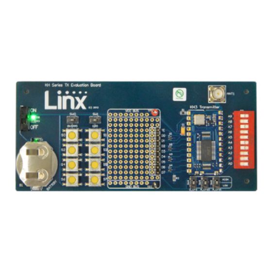
KH3 Series Basic Evaluation Kit *** = 315, 418 (Standard), 433MHz Figure 2: Ordering Information KH3 Series Transmitter / Encoder Evaluation Board Figure 3: KH3 Transmitter / Encoder Evaluation Board 1. Battery – 3VDC (use a CR2032-style battery only) 2. Power Switch 3. -
Page 7: Kh3 Series Receiver / Decoder Evaluation Board
KH3 Series Receiver / Decoder Evaluation Board Figure 4: KH3 Receiver / Decoder Evaluation Board 1. Battery – 3VDC (use 2 AAA style batteries) 2. Power Switch 3. Prototyping Area 4. Breakout Header 5. KH3 Series Receiver / Decoder Module 6. -
Page 8: Theory Of Operation
Decoder Evaluation Board The receiver board is powered by two AAA batteries. The data recovered by the KH3 Series receiver is internally decoded. If the settings of the 10-position DIP switch on the receiver board match the address setting of the transmitter board, the data lines are updated to match the state of the data lines (or pushbuttons) on the transmitter board. -
Page 9: Using The Kit
For this reason it is important to set the address to a unique configuration. Note: The KH3 Series has 10 address inputs which can be set to over a thousand combinations. It is extremely important to mix up the address logic, making the address more likely to be unique. -
Page 10: Development Using The Prototyping Area
Development Using the Prototyping Area In addition to their evaluation functions, the boards may also be used for product development. They feature a prototyping area for the addition of application-specific circuitry. This area has connections to V at the top and to ground at the bottom that can be used to power any circuitry that is added. -
Page 11: Range Testing
For applications where Part 15 limits are not applicable, R1 can be changed according to the attenuation graph in the KH3 Series Transmitter Data Guide. To achieve maximum range, keep objects such as your hand away from the antenna and ensure that the antenna on the transmitter has a clear and unobstructed line-of-sight path to the receiver board. -
Page 12: Using The Boards As A Design Reference
RSSI voltage with the transmitter turned off to determine if ambient interference is present. If this fails to resolve the issue, please contact Linx technical support. Using the Boards as a Design Reference The basic evaluation boards included in this kit are very simple, yet they illustrate some important techniques that should be incorporated into the board layout. -
Page 13: About Antennas
About Antennas The choice of antennas is one of the most critical and often overlooked design considerations. The range, performance, and legality of an RF link are critically dependent upon the type of antenna employed. Linx offers a variety of antenna styles that can be considered for a design. Included with the kit is a Linx CW Series connectorized whip antenna that should be connected prior to using the kit. -
Page 14: Kh3 Series Transmitter Evaluation Board Schematic
KH3 Series Transmitter Evaluation Board Schematic Figure 5: KH3 Series Transmitter / Encoder Evaluation Board Schematic – –... - Page 15 KH3 Series Receiver / Decoder Evaluation Board Schematic Figure 6: KH3 Series Receiver / Decoder Evaluation Board Schematic – –...
- Page 16 Disclaimer Linx Technologies is continually striving to improve the quality and function of its products. For this reason, we reserve the right to make changes to our products without notice. The information contained in this Data Guide is believed to be accurate as of the time of publication. Specifications are based on representative lot samples.
Need help?
Do you have a question about the KH3 Series and is the answer not in the manual?
Questions and answers