Table of Contents
Advertisement
Quick Links
Operating and
installation manual
REMKO PWW-EC series
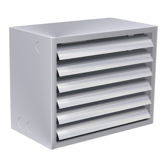
Hot water heaters with EC fan
PWW 30-2 EC, PWW 30-3 EC, PWW 30-4 EC, PWW 30-6 EC,
PWW 50-2 EC, PWW 50-3 EC, PWW 50-4 EC, PWW 50-6 EC,
PWW 80-2 EC, PWW 80-3 EC, PWW 80-4 EC, PWW 80-6 EC,
PWW 100-2 EC, PWW 100-3 EC, PWW 100-4 EC, PWW 100-6 EC
Edition EN - Z05
Read the instructions prior to performing any task!
Advertisement
Table of Contents

Subscribe to Our Youtube Channel
Related Manuals for REMKO PWW-EC Series


Summary of Contents for REMKO PWW-EC Series
- Page 1 Operating and installation manual REMKO PWW-EC series Hot water heaters with EC fan PWW 30-2 EC, PWW 30-3 EC, PWW 30-4 EC, PWW 30-6 EC, PWW 50-2 EC, PWW 50-3 EC, PWW 50-4 EC, PWW 50-6 EC, PWW 80-2 EC, PWW 80-3 EC, PWW 80-4 EC, PWW 80-6 EC,...
-
Page 3: Table Of Contents
Content Safety notes Unit description Unit installation Electrical connection 7-11 Heating medium connection Commissioning Shutdown Care and maintenance Repair Exhaust accessories 16-17 Intake accessory Accessory installation 18-19 View of the unit Spare parts list Intended use Customer service and guarantee Environmental protection and recycling Performance tables / unit curves 22-29... -
Page 4: Safety Notes
REMKO PWW Safety notes Unit description The units were subjected to The units must be installed away The units are stationary, indirectly ■ extensive material, functional and from traffic zones and installed loaded air heaters with Cu / quality inspections prior to delivery. -
Page 5: Unit Installation
Unit installation For safe unit installation, observe Brackets the following instructions: Brackets (KO) for wall and ceiling installation (2 pieces per unit) are inserted in the openings on the rear side of the unit and fastened to the The units are to be arranged ■... - Page 6 REMKO PWW Installation examples Recirculation / fresh air operation through the roof Recirculation / fresh air operation via the outside wall The recirculation intake duct and the intake piece are fastened to the Wall passage corresponding to the exterior wall by the customer.
-
Page 7: Electrical Connection
Electrical connection The motors are connected to a Ceiling installation The electrical unit connections may corresponding control system in only be established by authorised accordance with the corresponding In recirculation mode with console specialists in accordance with the circuit diagram. applicable regulations, observing the regulations from the local The corresponding power fuse in... - Page 8 REMKO PWW Circuit diagram PWW 30 EC GND 10V L1 N PE 11 14 1 Legend: A: Supply line with on-site fuse protection B: 0-10 V signal C: EC fan D: Terminal box Example connection of room temperature control RR 21.2 PWW 30 EC RR 21.2...
- Page 9 Circuit diagram PWW 50-80 EC 10V GND L1 N PE 11 14 1 Legend: A: Supply line with on-site fuse protection B: 0-10 V signal C: EC fan D: Terminal box Example connection of room temperature control RR 21.2 PWW 50-80 EC RR 21.2 L1 N PE 11 14 1...
- Page 10 REMKO PWW Circuit diagram PWW 100 EC 24V 10V L1 N PE 11 14 1 Legend: A: Supply line with on-site fuse protection B: 0-10 V signal C: EC fan D: Terminal box Example connection of room temperature control RR 21.2 PWW 100 EC RR 21.2...
- Page 11 Group controller PWW 100 EC PWW 30 EC PWW 50 EC / PWW 80 EC L1 N PE 11 14 1 L1 N PE 11 14 1 L1 N PE 11 14 1 0-10V When installing a group The minimum impedance of the ■...
-
Page 12: Heating Medium Connection
REMKO PWW Heating medium connection Connection to the hot water heating system Air inlet Air outlet Before connection to the on-site heating system, it must be ensured that the respective unit-specific Water inlet output requirements can always be provided. Water outlet The unit connection on the ■... -
Page 13: Commissioning
Commissioning Shutdown Before initial commissioning During initial commissioning Switch the operating switch for the relevant switchgear to the “Off” CAUTION All regulating, control and safety or “0” position. equipment must be checked for Commissioning can only take function and correct settings place once it has been assured during the initial commissioning. -
Page 14: Care And Maintenance
REMKO PWW Care and maintenance 3. Completely drain the In normal operation, the units Cleaning the units finned heat exchanger and are almost maintenance-free. Clean all intake openings and ■ disconnect the heating medium However, in order to guarantee discharge fins connections. -
Page 15: Exhaust Accessories
Exhaust accessories Standard design The units are equipped with horizontal individually adjustable air outlet fins as standard. The louvers can be easily unclipped for disassembly. ■ Exhaust louvers B Vertically individually adjustable air outlet fins for wall and ceiling discharge. The exhaust louvers B are mounted directly in front of the horizontal air exhaust louvers. -
Page 16: Intake Accessory
REMKO PWW Intake accessory Exterior air intake grate AG Intake air protection grid for fresh air intake through the exterior wall For the wall opening: Measurement a and b + approx. 15 mm Wall bracket WFM for the wall fastening of the unit with suction-side accessories... - Page 17 Intake accessory Outside air intake hood ALH for outside air intake through the roof Rain collar RK with intermediate duct piece in 1000 or 500 mm length 1000 1000 1000 1000 Elastic nozzle SG Flexible connection (vibration damping) between unit and air duct system.
-
Page 18: Accessory Installation
REMKO PWW Accessory installation Mixed air coffer MLK Filter coffer FK Frost protection thermostat FS The mixed air coffer MLK is The filter coffer with pocket filter The frost protection thermostat designed for both wall and ceiling is designed for direct mounting on is a precisely functioning water installation. - Page 19 The servo motor type KSP is economical extension for your the louvre axis. It is equipped with supplied with 230 V mains voltage. REMKO PWW unit and is a universal terminal block and is A transformer converts the mains designed for direct attachment to...
-
Page 20: View Of The Unit
REMKO PWW View of the unit We reserve the right to modify the dimensions and design as part of the ongoing technical development process. Spare parts list PWW 30 PWW 50 PWW 80 PWW 100 Designation EDP no. EDP no. -
Page 21: Intended Use
“Certificate of environment. structural design and equipment. guarantee” to REMKO GmbH & Our units are carefully packed Co. KG at the time when the units and delivered in stable transport The unit design allows for the use are purchased and commissioned. -
Page 22: Performance Tables / Unit Curves
REMKO PWW PWW 30 EC - Output tables - Technical data Type PWW 30-2 EC PWW 30-3 EC PWW 30-4 EC PWW 30-6 EC 230V/50Hz 230V/50Hz 230V/50Hz 230V/50Hz Motor 140W/1.25A 140W/1.25A 140W/1.25A 140W/1.25A Volt Control Power consumption m³/h 2280 1770... - Page 23 PWW 30 EC • Unit characteristics • Heating medium resistances Pressure differential characteristics D of the unit accessories: 1. Suction-side mounted accessories Component Type Mixed air coffer Filter coffer (clean filter) Average filter contamination Intermediate duct piece (per m) Exterior air intake grate Recirculating air intake shaping component Outside air intake hood...
- Page 24 REMKO PWW PWW 50 EC - Output tables - Technical data Type PWW 50-2 EC PWW 50-3 EC PWW 50-4 EC PWW 50-6 EC 230V/50Hz 230V/50Hz 230V/50Hz 230V/50Hz Motor 360W/1.43A 360W/1.43A 360W/1.43A 360W/1.43A Volt Control Power consumption m³/h 3850 2140...
- Page 25 PWW 50 EC • Unit characteristics • Heating medium resistances Pressure differential characteristics D of the unit accessories: 1. Suction-side mounted accessories Component Type Mixed air coffer Filter coffer (clean filter) Average filter contamination Intermediate duct piece (per m) Exterior air intake grate Recirculating air intake shaping component Outside air intake hood...
- Page 26 REMKO PWW PWW 80 EC - Output tables - Technical data Type PWW 80-2 EC PWW 80-3 EC PWW 80-4 EC PWW 80-6 EC 230V/50Hz 230V/50Hz 230V/50Hz 230V/50Hz Motor 360W/1.43A 360W/1.43A 360W/1.43A 360W/1.43A Volt Control Power consumption m³/h 6750 4620...
- Page 27 PWW 80 EC • Unit characteristics • Heating medium resistances Pressure differential characteristics D of the unit accessories: 1. Suction-side mounted accessories Component Type Mixed air coffer Filter coffer (clean filter) Average filter contamination Intermediate duct piece (per m) Exterior air intake grate Recirculating air intake shaping component Outside air intake hood...
- Page 28 REMKO PWW PWW 100 EC - Output tables - Technical data Type PWW 100-2 EC PWW 100-3 EC PWW 100-4 EC PWW 100-6 EC 230V/50Hz 230V/50Hz 230V/50Hz 230V/50Hz Motor 530W/2.34A 530W/2.34A 530W/2.34A 530W/2.34A Volt Control Power consumption Air volume m³/h...
-
Page 29: Calculation Examples
PWW 100 EC • Unit characteristics • Heating medium resistances Pressure differential characteristics D of the unit accessories: 1. Suction-side mounted accessories Component Type Mixed air coffer Filter coffer (clean filter) Average filter contamination Intermediate duct piece (per m) Exterior air intake grate Recirculating air intake shaping component Outside air intake hood... - Page 30 REMKO PWW Example calculation and explanation The heat outputs specified in the output tables change by: Reduced air volumes with additionally attached accessories such as (mixed air coffer, filter coffer, outlet nozzle, etc.). Observe pressure differential characteristics! Air heating correction...
- Page 31 Example calculation and explanation The following arises from the calculation example: 2. Heat output Q (kW) 3150 = 0.59 Air flow ratio 5360 With the ratio V to air volume V (output table value), the diagram Thermal power correction factor f = 0.72 “Thermal power correction”...
-
Page 32: Planning / Calculation / Units
Determination of the required heating capacity, outside air quantity and exhaust temperatures Heating capacity: The heating capacity Q of the REMKO heating units takes the following elements into consideration: 1. Heat demand Q of the room to be heated. (Calculation in accordance with DIN 4701 & 4108) 2. - Page 33 Planning • Calculation • Units Symbol Unit Explanation Heating capacity of the air heating unit Q = Q Heat requirement of the room to be heated Heat requirement for the heating of the outside air to room tempera- · ∆ ·...
-
Page 34: Unit Dimensions
REMKO PWW Unit dimensions = Water inlet (supply) = Water outlet (return flow) The water inlet (flow) must always be carried out on the "air outlet side". This is the case even if the units are rotated during installation and connected on the other side. -
Page 35: Technical Data
Technical data Series PWW 30-2 EC PWW 30-3 EC PWW 30-4 EC PWW 30-6 EC Motor 230V / 50Hz / 140W / 1.25A Power consumption Watt Air volume 2280 1770 1810 1530 1530 1350 1480 1320 Sound pressure level dB(A) Heating medium Inches ¾"... - Page 36 REMKO QUALITY WITH SYSTEMS Air-Conditioning | Heating | New Energies REMKO GmbH & Co. KG Telephone +49 (0) 5232 606-0 Hotline within Germany Klima- und Wärmetechnik Telefax +49 (0) 5232 606-260 +49 (0) 52 32 6 06-0 Im Seelenkamp 12 E-mail info@remko.de...
Need help?
Do you have a question about the PWW-EC Series and is the answer not in the manual?
Questions and answers