Table of Contents
Advertisement
Quick Links
• The installation of the product is carried out by the customer who purchases the product, according to the wiring diagrams,
installation information, etc. in this manual.
• Maintenance and repair should be done by the technicians authorized by the manufacturer firm.
• There must be minimum distance between the sensor and control unit. Avoid additions except the suitable connector unless it
needs.
• Keep away the sensor cable from as high power energy cables, contactor, motor, switched power supplies, inductive and capacitive
noisy supplies.
• Shielding edge of the sensor cable must be ground connected.
• Not to damage the sensor supply directions and voltage must be paid attention. Don't energize before all connections completed.
• Transport and storage should be at their original packaging and an ambient temperature of -25°C / + 85°C in such a way that they
will not be exposed to dust, humudity, impact, vibration, falling or water.
• Chemicals such as alcohol, thinner etc. should not be used for cleaning the product. The product should be wiped with a damp
cloth.
• The product may be damaged and may become unusable if used outside of the specifications in the user manual.
• The product will be out of warranty if used outside of the specifications in the user manual and opened or repaired other
than authorized services.
Never make or undo electrical connections to the sensor when voltage is applied, otherwise this may result in damage to
devices. AWP 810 can be optionally requested as single output or redundant.
0-10V or POTENTIOMETER Connection
Signal
Cable Color
Earth
Silver
+V
Red
0V
Black
0-10V / Pot
Yellow
-
-
* 1 pcs M12 5 pin male connector is used as standard for single output models
* Redundant models have two outputs. 1 pcs M12 5 pin male and 1 pcs M12 5 pin female sockets are used as standard.
* Different socket models can be requested optionally.
KK-AWP.012 03.03.21 Rev No:3
DRAW WIRE SENSOR USER MANUAL
GENERAL INFORMATION
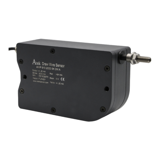
AWP 810 series draw wire sensors; consists of a rotary potentiometer which is controled by
stainless steel wire. They make measurement by pulling and rewinding stainless steel wire.
Different measuring lengths from 2000 mm to 5100 mm are available. They converts linear
motion to potentiometric output.
The "A" series, works with 24VDC supply and gives of 4-20 mA analog output with the help of the
converter card.
The "V" series, works with 24VDC supply and gives of 0-10 VDC analog output with the help of the
converter card.
Optionally, redundant output, different non-standard measuring lengths, cable length or socket
model can be requested.
ELECTIRICAL CONNECTIONS
M12 5 pin male socket
Pin 1
Pin 2
Pin 3
Pin 4
Pin 5
WARNINGS
4-20 mA Connection
Signal
Cable Color
Earth
+V
-
4-20 mA
-
M12 5 Pin Male Socket
AWP 810
M12 5 pin male socket
Silver
Pin 1
Red
Pin 2
-
Pin 3
Yellow
Pin 4
-
Pin 5
M12 5 Pin Female Socket
1
Advertisement
Table of Contents

Subscribe to Our Youtube Channel
Related Manuals for Atek AWP 810 Series


Summary of Contents for Atek AWP 810 Series
- Page 1 AWP 810 GENERAL INFORMATION AWP 810 series draw wire sensors; consists of a rotary potentiometer which is controled by stainless steel wire. They make measurement by pulling and rewinding stainless steel wire. Different measuring lengths from 2000 mm to 5100 mm are available. They converts linear motion to potentiometric output.
- Page 2 MECHANICAL MOUNTING 1-The product should be mounted to the relevant area with 2 units M6 stud bolts(1) and nuts(5) from the mounting holes (2) according to the mounting directions shown on page 3. 2-The sensor wire should be pulled towards the position to be connected with the barrel bolt (4).
- Page 3 MOUNTING AND USAGE WARNINGS 1. Never release the wire after pulling. Otherwise, the coil spring will be damaged. 2. Mount the sensor according to the mounting directions shown below. 3. If there is a trickle of water (like a rain), the wire outlet must not be a drip of water upstream. If needed please use guide rollers.
- Page 4 Explanation: AWP 810 series, 3000 mm stroke, 5K resistance, 2 pcs M12 5 pin female socket, current output, redundant output Sample Code 2: AWP-810-3000-5K-S13FM-DUAL Explanation: AWP 810 series, 3000 mm stroke, 5K resistance, 1 pcs M12 5 pin female + 1 pcs M12 5 pin male socket, potentiometric output, redundant output Manufacturer Firm’s Title, Address Details...
Need help?
Do you have a question about the AWP 810 Series and is the answer not in the manual?
Questions and answers