Table of Contents
Advertisement
Quick Links
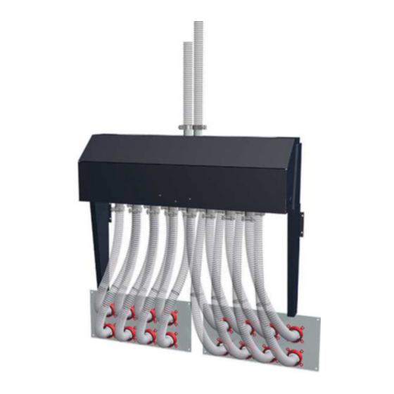
Installation and operating instructions
Pellet suction system RS 4 / RS 8
Model
Fire protection package
Translation of original German version of installation and operating instructions for technicians and
operators.
Read and follow all instructions and safety instructions.
All errors and omissions excepted.
M1890721_en | Edition 14/05/2021
Advertisement
Table of Contents


Need help?
Do you have a question about the RS 4 and is the answer not in the manual?
Questions and answers