Advertisement
Part Numbers:
CD-DS-ST-B
CD-DS-ST-C
CD-DS-ST-CC
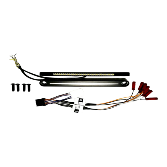
Package Contents:
- Dynamic Strips™ Turn Signals (pair)
- ST Harness L/R (1)
- 5/16"-24 X 3/4" Screws (4)
Fits: 1999-2017 HD Fatboy® and Slim®
Fits: 1999-2017 HD Heritage and Deluxe® ( stock passing
lamps removed)
ATTENTION
Please read all Information below before Installation
Warning:
Disconnect negative battery cable from battery; refer to
owner's manual. Failure do to so may result in electrical shock, injury
or fire. Secure negative battery cable away from positive side of
battery and all other positive voltage sources on vehicle.
Safety First:
Always wear appropriate safety gear including safety
glasses when performing any electrical work. It is highly recom-
mended that safety glasses be worn throughout this installation
process. Be sure vehicle is on level surface, secure and cool.
Important: This product is designed and intended for use as
auxiliary lighting only. It is NOT intended to replace any original
equipment lighting installed on the vehicle and should not be used
for that purpose. This product must be wired so that it does not
interfere with any original equipment lighting.
Note: The location of the factory harness plug may vary from model
to model and year to year. It will be located under the gas tank on
either the left or the right side of the frame support. Consult model
year owners manual to determine where factory plug is located.
Note: Installation of this product requires partial removal of the gas
tank. See owners manual or detailed service manual for instructions
on this procedure. If you are not comfortable performing this task
yourself, have this product installed by a qualified Harley-Davidson
mechanic or dealer.
Questions? Call us at: 1 (800) 382-1388
Custom Dynamics® Dynamic Strips™ Turn Signals
We thank you for purchasing the Custom Dynamics® Dynamic
Strips™ Turn Signals. Our products utilize the latest technology
and high quality components to ensure you the most reliable ser-
vice. We offer one of the best warranty programs in the industry
and we back our products with excellent customer support, if you
have questions before or during installation of this product please
call Custom Dynamics® at 1(800) 382-1388.
1
Refer to the manufacturer detailed service manual for
instructions on removing the gas tank. We are not removing
it all the way, only sliding it back about 5 inches so that we
have access to the 8 pin turn signal harness plug located
on the right side of the bike, highlighted above. It will be
behind the rubber frame cover.
2
Remove the connector from the connector plate, then plug
the male end of the ST-HARNESS into to the plug. Re-
mount the plug to the connector plate when complete.
M-TH 8:30AM-5:30PM / FR 9:30AM-5:30PM EST
8 Pin
Connector
Connector
Plate
09-2017
Advertisement
Table of Contents

Related Manuals for Custom Dynamics Dynamic Strips CD-DS-ST-B


Summary of Contents for Custom Dynamics Dynamic Strips CD-DS-ST-B
- Page 1 Custom Dynamics® Dynamic Strips™ Turn Signals Installation Instructions We thank you for purchasing the Custom Dynamics® Dynamic Strips™ Turn Signals. Our products utilize the latest technology and high quality components to ensure you the most reliable ser- vice. We offer one of the best warranty programs in the industry...
- Page 2 Installation Instructions - Page 2 Twist Left side of the bike Identify the LEFT side ST-HARNESS connections labeled The wires exiting the ST-HARNESS are paired with shrink with a sticker marked “L”, they need to be routed over to tube coverings. Take the Yellow and black paired wires and the left side of the bike.
- Page 3 Installation Instructions - Page 3 Remove the tie-wraps that secure the Dynamic Strips™ Use a center punch at the marked location to ensure a together and un-wrap the wires. Take the right strip and guide for the drill bit. Repeat for the other side. place it over the 2 bolts that secure the cover.
- Page 4 Installation Instructions - Page 4 Note that there is a gap between the front plate and the Now that the drilling is complete, we must make sure that fork. Using the side rail, turn it over so that the back side is there are no sharp rough edges on all parts of the cover that facing outward (the side you don’t see when installed), then could cut the wires from the Dynamic Strips™.
- Page 5 Installation Instructions - Page 5 Install the rear cover back to the bike. Insert the wires from the Dynamic Strip™ into the holes in the covers. Pull wire slack though the other side. Repeat this for the other side. Route the wires to the ST-HARNESS connectors. Using the included mounting screws, secure the Dynamic Strip™...
- Page 6 Installation Instructions - Page 6 Use the wiring diagram for connecting the Dynamic Strips™ wires to the ST-HARNESS. You can wrap the red connectors with electrical tape or they may be covered with heat shrink tubing, though neither is mandatory. Note: The secondary connector on Left Right...
- Page 7 Installation Instructions - Page 7 Tuck Wires up Note: This is a very IMPORTANT step. DO NOT SKIP. into the rear of the fork cover Grab both sets of wires with the closed end of your fingers and push them into the back of the fork cover as shown in the photo. This should give about 5-6 inches of slack in the wires to allow the handlebars to turn freely.
Need help?
Do you have a question about the Dynamic Strips CD-DS-ST-B and is the answer not in the manual?
Questions and answers