Advertisement
Part Number: GEN-SMART-TPU-SS8
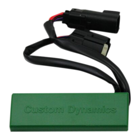
Package Contents:
- SMART Triple Play® Module with Posi-Lock™ Connectors
- Instructions
Fits: 2010-2012 Street Glide® CVO™, 2013 Road King®
CVO™, 2009 Road Glide® CVO™ and 2012-2013 Road
Glide® Custom CVO™ with OEM LED Panels
ATTENTION
Please read all warning Information before Installation
Important: This system is designed to work with Custom Dynam-
ics® BAGZ™ LED Lights. They will not work with the any Amber/
Red saddle bag lights.
Caution: This unit is designed for a maximum load of 27 watts
per channel. Do no exceed 27 watts per left turn signal output, 27
watts per right turn signal output, and 27 watts per brake signal
output. Overloading unit could cause damage to the unit and
cause the unit to malfunction.
Important: A load equalizer or Signal Stabilizer™ is required for
the Smart Triple Play® to function properly. The load equalizer
MUST be installed on the input side of the Smart Triple Play®
unit. NEVER install a load equalizer downstream of this unit.
Important: Module must be secured after installation. Find safe
area away from any moving parts and out of the way of normal
operation of the bike. Use Tie-wraps, tape, (not included) or other
means to secure. Custom Dynamics® is not liable for damage to
the module or the bike as a result of improperly securing the
module.
Questions? Call us at: 1 (800) 382-1388
Custom Dynamics® Smart Triple Play®
Installation Instructions
We thank you for purchasing the Custom Dynamics® Smart Triple
Play®. Our products utilize the latest technology and high quality
components to ensure you the most reliable service. We offer one of
the best warranty programs in the industry and we back our prod-
ucts with excellent customer support, if you have questions before
or during installation of this product please call Custom Dynamics®
at 1(800) 382-1388.
Installation:
Note: The Smart Triple Play® will cause the BAGZ™ and OEM LED
Panels to have a full contrast turn signal flash and to flash/strobe
when the brake is applied.
1.
Secure motorcycle on level surface. Disconnect negative battery
cable from the battery. Locate the lighting connector under the
seat.
2.
Remove the MPR-SS8-PLUG plug and play adapter for
BAGZ™ and plug the Smart Triple Play® Module, in-line, into
the rear lighting harness under the seat. Signal Stabilizer™ or
load equalizer should be installed on the input side of the Smart
Triple Play® unit (page 3).
Note: Wiring Diagram on page 3.
3.
Cut and remove the 3 pin plug from each LED BAGZ™ light to
expose the black, yellow, and brown (right side) or purple (left
side) wires. Cap off the yellow wire from each BAGZ™ light.
4.
Connect the pigtail output wires from the Smart Triple Play®
using the supplied Posi-Lock™ connectors to the exposed black
and brown (right side) or (left side) purple wires on the Custom
Dynamics® BAGZ™ LEDs.
5.
Connect the brown wire to the right side (brown) LED high wire
[+]. Connect the purple wire to the left side (purple) LED high
wire [+]. Connect the black wire of left side LED neg. and the
right side LED neg. to the [ - ] black wire of the unit.
6.
Re-connect the battery's negative battery cable to the battery.
7.
Locate a secure place for the Smart Triple Play® unit that will
not interfere with the secure placement of the seat or side cover.
Secure with tie-wraps, tape or other means so that unit cannot
move.
8.
Program Smart Triple Play® and select desired brake strobe
pattern. See Programming Instructions on page 2.
9.
Test for proper run, brake and turn function.
M-TH 8:30AM-5:30PM / FR 9:30AM-5:30PM EST
12-2017
Advertisement
Table of Contents

Related Manuals for Custom Dynamics Smart Triple Play GEN-SMART-TPU-SS8


Summary of Contents for Custom Dynamics Smart Triple Play GEN-SMART-TPU-SS8
- Page 1 Use Tie-wraps, tape, (not included) or other means to secure. Custom Dynamics® is not liable for damage to the module or the bike as a result of improperly securing the module.
- Page 2 Installation Instructions - Page 2 Testing for Proper Operation: Locate the two switches and rotary dial on the Smart Triple Play® module. Be sure the rotary dial is set to position 0. There is a small arrow on the rotary dial, this is the pointer that should now be at position 0.
- Page 3 Installation Instructions - Page 3 Flash Pattern Information: Pattern 5: Quad Strobe, Solid for 1 Sec- ond, then Quad Strobe, Solid for 3 Sec- onds, then Repeat LED Only Pattern 4: Quad Strobe then Solid Pattern 6: Blaster X Pattern for 6 for 1 Second then Quad Strobe seconds, then Solid LED Only...
Need help?
Do you have a question about the Smart Triple Play GEN-SMART-TPU-SS8 and is the answer not in the manual?
Questions and answers