Chapters
Table of Contents

Subscribe to Our Youtube Channel
Related Manuals for Panasonic AJ-SPD850E


Summary of Contents for Panasonic AJ-SPD850E
-
Page 1: Operating Instructions
Before operating this product, please read the instructions carefully and save this manual for future use. S0704N7125 -M Printed in Japan Operating Instructions Memory Card Recorder Model No. ENGLISH VQT0L05-4... - Page 2 For AJ-SPD850P IMPORTANT “Unauthorized recording of copyrighted television programmes, video tapes and other materials may infringe the rights of copyright holders and contravene copyright laws.” indicates safety information. THIS EQUIPMENT MUST BE GROUNDED To ensure safe operation, the three-pin plug must be inserted only into a standard three-pin power outlet which is effectively grounded through normal household wiring.
- Page 3 Canada. CAUTION: Operation at a voltage other than 120 V AC may require the use of a different AC plug. Please contact either a local or foreign Panasonic authorized service center for assistance in selecting an alternate AC plug.
-
Page 4: Caution For Ac Mains Lead
For AJ-SPD850E Caution for AC Mains Lead FOR YOUR SAFETY PLEASE READ THE FOLLOWING TEXT CAREFULLY. This product is equipped with 2 types of AC mains cable. One is for continental Europe, etc. and the other one is only for U.K. -
Page 5: Operating Precaution
For AJ-SPD850E IMPORTANT “Unauthorized recording of copyrighted television programmes, video tapes and other materials may infringe the rights of copyright holders and contravene copyright laws.” Operating precaution Operation near any appliance which generates strong magnetic fields may give rise to noise in the video and audio signals. -
Page 6: Table Of Contents
(Details are given in the original (English-language) text.) To obtain the source codes, go to the following home page:http://panasonic.biz/sav/ The manufacturer asks users to refrain from directing inquiries concerning the source codes they have obtained and other details to its representatives. -
Page 7: Introduction
Introduction The AJ-SPD850 is a memory card recorder that has five slots for cards (such as the AJ-P2C002SG which is sold separately) that conform to the PC card type II standard. It can record and play video and audio in the DVCPRO50, DVCPRO, and DV compression formats. -
Page 8: Features
Features Recording and play of files on memory cards The memory card recorder can record to and play video and audio on memory cards (such as the AJ-P2C002SG which is sold separately; henceforth referred to as “P2 cards”) in the DVCPRO50, DVCPRO, and DV compression formats. - Page 9 For the latest information on P2 cards and SD memory cards: For the latest information not available in the Operating Instructions, visit the P2 Support Desk at the following Web sites. For Japanese: http://panasonic.biz/sav/ For English: https://eww.pavc.panasonic.co.jp/pro-av/ (1 Card) DVCPRO50 (4-channel audio) approx.
-
Page 10: Control Reference Guide
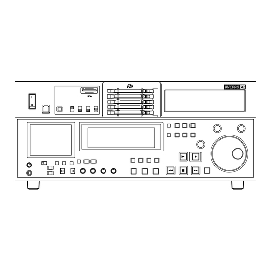
Control reference guide Front panel — Upper section PULL DVCPRO 50 POWER DVCPRO USB 2.0 REMOTE SUPER REC INH POWER switch Use when switching between ON and OFF of the power. USB 2.0 connector (Type B) Use when connecting a personal computer (See page 20). REMOTE button and REMOTE display Use when operating the memory card recorder under external control or copying files on P2 cards through the... - Page 11 Control reference guide (continued) Front panel — Under section (1/3) FULL/FINE HEADPHONES AUDIO MIX AUDIO MON SEL 1&2 3&4 REC CH1/3 CH1/3 CH2/4 UNITY PULL REC CH2/4 CH1/3 CH2/4 AUDIO VOL SEL 3.5-inch color LCD monitor Use thumbnails and other features to find and check video and audio.
- Page 12 Control reference guide (continued) Front panel — Under section (2/3) FULL/FINE HEADPHONES AUDIO MIX AUDIO MON SEL 1&2 3&4 REC CH1/3 CH1/3 CH2/4 UNITY PULL REC CH2/4 CH1/3 CH2/4 AUDIO VOL SEL MENU button Press to show the setup menus on the 3.5-inch color LCD and the TV monitor (when using the VIDEO OUT 3 or SDI OUT 3 connector (optional)).
- Page 13 Control reference guide (continued) Front panel — Under section (3/3) METER FULL/FINE HEADPHONES AUDIO MIX AUDIO MON SEL 1&2 3&4 REC CH1/3 CH1/3 CH2/4 UNITY PULL REC CH2/4 CH1/3 CH2/4 AUDIO VOL SEL INPUT SELECT buttons Switch the video and audio input signals. You can also switch the video input signals to the internal signal selected at setup menu No.
- Page 14 Control reference guide (continued) When the AUDIO MIX switch setting, the setting is switched by one step in the sequence of A → B → C each time the REC CH2/4 button is pressed. OFF) CH1/3 CH2/4 The CH4 signals are recorded on CH4.
-
Page 15: Display
Use the METER selector button to switch the audio level display between FULL and FINE mode (See page 14). (For AJ-SPD850E, reference level: –18 dB) Each of the dots “ REC INH For AJ-SPD850P... -
Page 16: Rear Panel
Control reference guide (continued) Rear Panel (1/2) AC IN SIGNAL AC IN socket Connect one end of the power cord supplied to this socket and the other end to the power outlet. DIGITAL AUDIO IN and OUT connectors These are the input and output connectors for digital audio signals that comply with the AES/EBU standards. - Page 17 Control reference guide (continued) Rear Panel (2/2) CH1•2 AC IN CH3•4 CH1•2 CH3•4 SIGNAL Cool the memory card recorder. If the fan stops, “E-10” appears on the counter display. SIGNAL GND terminal Connect to the signal ground terminal on the component connected to the memory card recorder to minimize noise.
-
Page 18: Recording And Playing
Recording and playing Inserting P2 cards Note: Before using the unit for the first time, be absolutely sure to set the internal clock using setup menu item No.069 (CLOCK SET). (1) Turn the POWER switch of the memory card recorder on (2) Press a card in a P2 card slot until the EJECT button pops out (3) Push the EJECT button that has popped out... -
Page 19: Protecting Against A Possible Erasure
Recording and playing (continued) Protecting against a possible erasure Switch the write-protect switch of the P2 card to [PROTECT]. Write-protect switch PROTECT Notes: • Any attempt to change the position of the write-protect switch during recording or playback or while the card data is being accessed will have no effect until the recording or playback is completed or the card data is no longer being accessed. -
Page 20: Connections
Connections Example of the memory card recorder and DVCPRO VTR Source machine: Set the CONTROL switch on the front panel to [REMOTE] (the memory card recorder : AJ-SPD850). Recorder: Set the CONTROL switch on the front panel to [LOCAL] (VTR : AJ-SD955 or others). Reference signal generator Source machine... -
Page 21: Jog/Shuttle (Search Dial)
Jog/Shuttle (Search dial) Locate the edit points. Each time it is pressed, it is set alternatively to the SHTL/SLOW mode or the JOG mode, and the JOG, SHTL or SLOW lamp lights. When the power is turned on, the search dial will not operate unless it is first returned to the STILL position. Jog mode (1) Press the search dial so that it remains pressed in... -
Page 22: Working With Clip Thumbnails
Working with clip thumbnails A clip is a piece of data containing video and audio from a single video recording, as well as additional information such as voice memos and meta-data. This unit allows the following operations to be performed using the search dial, FF button, REW button, SHIFT button and SET button while you are checking out the thumbnails of clips displayed on the LCD monitor. -
Page 23: Thumbnail Screen
Working with clip thumbnails (continued) Thumbnail screen Press the THUMBNAIL button to display the thumbnail screen on the LCD. Press the THUMBNAIL button again to return to the normal display. Press the MENU BAR button on the thumbnail screen to change the pointer to a menu bar. - Page 24 Working with clip thumbnails (continued) Menu bar The menu bar contains menu items for performing clip operations, switching/setting the thumbnail display, etc. To use the menu bar, press the MENU BAR button on the thumbnail screen. Menu items are selected with the search dial, FF button, REW button or SET button.
- Page 25 Working with clip thumbnails (continued) Switching the thumbnail display It is possible to switch the thumbnail screen so that only clips meeting certain conditions are displayed. (1) Press the THUMBNAIL button. The thumbnail screen is displayed on the LCD. (2) Press the MENU BAR button. The pointer moves to the menu bar.
-
Page 26: Voice Memos
Working with clip thumbnails (continued) Voice memos A voice memo is audio data which is separate from the original recorded audio and can be added to a clip independently of the original recorded audio. Voice memos added using a camera recorder can be played. Note: Voice memos cannot be added using this memory card recorder. -
Page 27: Repairing Clips
Working with clip thumbnails (continued) Repairing clips This section describes how to repair bad clips which were have been damaged for reasons such as a sudden power outage during recording. Note: Only clips with yellow bad clip indicators can be repaired. - Page 28 SD memory cards using a PC. Download the latest update version of P2 viewer from the following URL and install it to your PC: http://panasonic.biz/sav/p2 Regarding SD memory cards to be used, see “Cautions in using SD memory cards” (page 27).
- Page 29 Working with clip thumbnails (continued) <Selecting the USER CLIP NAME recording method> From the menu bar, select [OPERATION] → [DEVICE SETUP] → [META DATA] → [USER CLIP NAME] item. Either [TYPE1] or [TYPE2] can be selected as the USER CLIP NAME recording method. [TYPE1] USER CLIP NAME to be When clip metadata has...
- Page 30 Working with clip thumbnails (continued) Network settings Perform the network settings. (1) Press the THUMBNAIL button. The thumbnail screen is displayed on the LCD. (2) Press the MENU BAR button, and select the following from the menu bar: [OPERATION] →[DEVICE SETUP] → [NETWORK] →[MANUAL]. Then select [IP ADDRESS] →[DHCP ON]/[DHCP OFF].
- Page 31 Working with clip thumbnails (continued) Clip information Various clip information is displayed in this area. START TC: The time code value corresponding to the start of recording is displayed here. START UB: The user’s bit value corresponding to the start of recording is displayed here. TIME: The time at the start of recording is displayed here.
-
Page 32: Format Error
Working with clip thumbnails (continued) Contents of P2 Card Status Display Settings From the menu bar, select [PROPERTY], then [CARD STATUS]. The following screen is displayed. When REMAIN has been selected Write protect mark If the P2 card containing the clip is write-protected, a mark is displayed here. - Page 33 Working with clip thumbnails (continued) Displaying the device properties The statuses of the SD memory card, LAN, metadata and DVD drive can be checked. <SD memory card status display> From the menu bar, select [PROPERTY] → [DEVICES] → [SD CARD]. If the format is compatible with SD standards, the message “SD STANDARD: SUPPORTED”...
-
Page 34: Play List
Play List The play list function enables only particular parts of the images and sound recorded on five P2 cards to be selected and the selected parts to be played in any order using only the unit by operating the IN, OUT and ENTRY buttons on the front panel. - Page 35 Play List (continued) Overview of play list operations Play lists can be created on the play list screen or event screen. Press the PLAYLIST button to switch to the play list screen or press the EVENT button to switch to the event screen. On the event screen, you can register or change the IN and OUT points while viewing the images.
-
Page 36: Creating A Playlist
Play List (continued) Creating a play list Registering events (1) Press the PLAYLIST button in the stop mode to switch to the play list screen. (2) Move to the event number corresponding to the event you want to register. The pointer can be moved faster by turning the search dial while holding down the SHIFT button. - Page 37 Play List (continued) Changing events On the play list screen, move the pointer to the number of the event to be changed, and press the EVENT button to switch to the event screen. Play the images, and press the IN or OUT + ENTRY buttons to change the IN or OUT point.
- Page 38 Play List (continued) Importing and storing play lists Importing play lists from an external source (1) Press the PLAYLIST button to switch to the play list screen. (2) Open the OPERATION sub menu and select IMPORT. (3) Select the import destination. [SLOT1-SLOT5]: The play list data stored on any of the P2 cards in slots 1 to 5 is selected.
-
Page 39: List Of Shortcuts
Play List (continued) Selecting the mode in which to access clips in the normal mode (the mode where the playlist function has been exited) The method used to access the clips in the normal mode can be changed. Set this to use the playlist you have created as material for the player in the editing system which employs the RS-422A interface. -
Page 40: Setup (Initial Settings)
Setup (Initial settings) The memory card recorder’s main settings are performed while making selections using a system of menus. If a TV monitor has been connected to the VIDEO OUT 3 connector or SDI OUT 3 connector (optional) on the rear panel and the SUPER switch is set to [ON], the setting menus are displayed on the TV monitor. -
Page 41: Setup Menus
Setup menus The memory card recorder can hold five user files, each of which has its own specific menu settings, and one of these files can be selected for use. Changing the file (1) Press the MENU button (2) Press the FF button while holding down the DIAG (or SHIFT) button to switch to the next user file or press the REW button while holding down the DIAG (or SHIFT) button to return to... -
Page 42: Loading User Files
Setup menus (continued) Loading user files The contents of the USER2, USER3, USER4 or USER5 file can be copied (loaded) into the USER1 file. Also, the contents of the USER1 file can be copied (saved) into the USER2, USER3, USER4 or USER5 file. Load/save USER 1 USER 2... -
Page 43: System Menu
Setup menus (continued) SYSTEM menu No./Item Description Coarse adjustment of system phase: 90 ° units SYS SC COAR. Note: 0000 If setting operation is 0001 performed, the setting 0002 180 value does not return to 0003 270 factory (default) setting. Fine adjustment of system phase: Variable range ±45 °... -
Page 44: User Menus
Setup menus (continued) SYSTEM menu No./Item Description This adjusts the brightness of the LCD monitor on the front panel. BRIGHT 0000 –7 0007 0014 Note: If setting operation is performed, the setting value does not return to factory (default) setting. This adjusts the contrast of the LCD monitor on the front panel. -
Page 45: [625I System]
Setup menus (continued) USER menu <BASIC> No./Item Description This selects what information is to be provided by the time code and other DISPLAY SEL superimposed displays output from the VIDEO OUT 3/SDI OUT 3 connector (optional). 0000 TIME : Data only. (The data indicates the value for whichever of CTL, TC or UB currently selected by the COUNTER button.) -
Page 46: Clock Set
Setup menus (continued) USER menu <BASIC> No./Item Description This sets the memory card recorder’s recording and playback format. SYS FORMAT 0000 50M : DVCPRO50 (50 Mbps) is selected. 0001 25M : DVCPRO (25 Mbps) is selected. 0002 DV : DV (25 Mbps) is selected. Note: The format complies with the setting of this menu item when the card is ejected. - Page 47 Setup menus (continued) USER menu <BASIC> No./Item Description Sets the time difference from the world standard time. TIME ZONE 0000 00:00 0001 +00:30 0002 +01:00 0050 –00:30 Refer to the table below, and select the setting which corresponds to the local time.
-
Page 48: Operation
Setup menus (continued) USER menu <OPERATION> No./Item Description This selects the direct search dial operation. SEARCH ENA 0000 DIAL : For direct search dial operations. 0001 KEY : Operation is not transferred to the search mode unless the search button is pressed. - Page 49 Setup menus (continued) USER menu <OPERATION> No./Item Description This selects the EE mode output signals. EE MODE SEL 0000 NORMAL : Signals are output with a delay equivalent to the length of internal signal processing. 0001 THRU : Signals are output directly, without internal processing, and so are output with no delay.
-
Page 50: Interface
Setup menus (continued) USER menu <INTERFACE> No./Item Description This selects whether the REMOTE (9P) connector functions when the 9P SEL REMOTE button is lit. 0000 OFF : Connector does not function. 0001 ON : Connector functions. This sets the ID information to be returned to the controller. -
Page 51: Edit
Setup menus (continued) USER menu <EDIT> No./Item Description This selects STD or NON-STD in accordance with the composite input STD/NON-STD signal. 0000 AUTO : Standard/non-standard signals are automatically processed. 0001 STD : Standard signals are processed. (Forced STD) 0002 N-STD : Non-standard signals are processed. -
Page 52: Time Code
Setup menus (continued) USER menu <TIME CODE> No./Item Description This selects whether to output the VITC signal at the positions selected VITC BLANK by setup menu items No. 501 (VITC POS-1) and No. 502 (VITC POS-2). 0000 BLANK : VITC signals are not output. 0001 THRU : VITC signals are output. -
Page 53: Video
Setup menus (continued) USER menu <TIME CODE> No./Item Description This is used to switch the phase of the time code, which is output from TC OUT REF the TIME CODE OUT connector, for the external LTC input when the TCG switch is at the “EXT”... -
Page 54: Wide Select
Setup menus (continued) USER menu <VIDEO> No./Item Description This selects whether to superimpose EDH onto the SDI output signals. 0000 OFF : EDH is not superimposed. 0001 ON : EDH is superimposed. Note: Even when ON is selected for this setting, EDH is not superimposed onto the signals output from the SDI OUT 3 connector (optional) if the SUPER switch... - Page 55 Setup menus (continued) USER menu <VIDEO> No./Item Description For setting 7.5% setup processing to be performed on input and output signals SETUP 25 in the DVCPRO (25 Mbps) mode. (For AJ-SPD850P) When the STOP button is pressed, operation is transferred to the sub- screen, and the setup level is set for each output.
-
Page 56: Audio
Setup menus (continued) USER menu <VIDEO> No./Item Description This selects whether or not to record the UMID information on the card. UMID REC 0000 OFF : UMID information is not recorded on the card. In addition, EE output signals are blanked. 0001 ON : UMID information is recorded on the... - Page 57 Setup menus (continued) USER menu <AUDIO> No./Item Description This selects the audio monitor output (Lch) reference level switching. MONIL OUT 0000 0001 0002 –20dB This selects the audio monitor output (Rch) reference level switching. MONIR OUT 0000 0001 0002 –20dB This selects whether to link the volume level of the audio monitor MONI OUT...
-
Page 58: Blank
Setup menus (continued) USER menu <V BLANK> No./Item Description Used to select the number of AUDIO channels for DVCPRO (25 Mbps) or 25M REC DV (25 Mbps) recording. 0000 2CH: Records on two channels. 0001 4CH : Records on four channels. Note: Four-channel recording is always used with DVCPRO50 (50 Mbps). - Page 59 Setup menus (continued) USER menu <V BLANK> No./Item Description This selects the mode for recording signals on additional lines. ADD LINE 50 0000 OFF : No signals are recorded on additional lines. 0001 YC422 : The 422 mode signals are recorded on 2 lines.
-
Page 60: No. 801: Add Line
Setup menus (continued) USER menu <V BLANK> No./Item Description This selects the method used to detect the lines in which the teletext TELETEXT signals are to be recorded. 0000 OFF : The teletext signals are not recorded. 0001 AUTO : The teletext signals are automatically detected and recorded. - Page 61 Setup menus (continued) USER menu <V BLANK> Number of lines which can be set for TELETEXT • When 25 Mbps is the recording/playback format. Number of lines which can be set [525i system] No. 800: 660: ADD LINE 25 setting value UMID REC setting value YC422 YC411...
-
Page 62: Menu
Setup menus (continued) USER menu <MENU> No./Item Description This selects the user file whose contents will be loaded into USER1. LOAD 0000 USER2 : The USER2 file contents are loaded. 0001 USER3 : The USER3 file contents are loaded. 0002 USER4 : The USER4 file contents are loaded. -
Page 63: Time Code, User Bit And Ctl
Time code, user bit and CTL Time code The time code is used when the time code signal generated by the time code generator (time code signal generator) is to be recorded. The time code values are indicated using the display and superimpose functions. -
Page 64: Superimpose Screen
Superimpose screen The control signals, time code, etc. are displayed using abbreviations. TV monitor Abbreviations: CTL : Control signal count value TCR : Time code data recorded in the SBC area UBR : User bit data recorded in the SBC area TCG : Time code data of the time code generator UBG : User bit data of the time code generator Note:... -
Page 65: Video Output Signals And Servo Reference Signal
Video output signals and servo reference signal This section explains how the output signals and servo reference signal are selected. External synchronization of video output signals The video output signals are output in synchronization with the REF VIDEO input signal or video input signal. As shown in the figure below, this signal is selected in accordance with the setup menu settings, deck mode and availability of the video input signal. -
Page 66: Audio V Fade Function
Audio V fade function When the settings below are selected for audio processing between clips or events (setup menu No.727: PB FADE) at times such as during clip selection and playback or play list playback, V fade or cut processing is performed for these sections during playback. -
Page 67: Audio Recording Channel And Monitor Output Selection
Audio recording channel and monitor output selection Audio recording channel The audio is selected as shown below by using the AUDIO MIX switch, REC CH1/CH3 and REC CH2/CH4 buttons on the front panel. Recording Recording signal track CH1 input/CH2 input/CH1 input+CH2 input CH1 input/CH2 input/CH1 input+CH2 input CH3 input/CH4 input/CH3 input+CH4 input CH3 input/CH4 input/CH3 input+CH4 input... -
Page 68: Rack Mounting
For the installation rails, it is recommended that the 18-inch rail and bracket (model number CC3061-99-0400) by Chassis Trak be used. (The complete slide rail and bracket deck is not available from Panasonic.) For further details, consult your dealer. (1) Attach the inner members of the slide rails Refer to the figure below for the locations where the screws are to be attached. -
Page 69: Condensation
Condensation Condensation occurs due to the same principle involved when droplets of water form on a window pane of a heated room. It occurs when the deck or card is moved between places where the temperature or humidity varies greatly or when, for instance: •... -
Page 70: Error Messages
Error messages When a warning occurs in this unit, the error number is indicated on the counter display. Open the DIAG menu to display a description of the error on the counter display or monitor TV. When an operational malfunction has occurred in the unit, the error number flashes on the counter display. - Page 71 Error messages (continued) “WARNING” information display • A warning message is displayed whenever a warning occurs. When warnings have not been detected, “NO WARNING” is displayed. • When multiple warning occur, the descriptions for each warning can be checked by turning the search dial. If “T&S&M”...
- Page 72 Error messages (continued) If “E- ” lights up in the monitor display, the contents are displayed when the DIAG-MENU is opened. Monitor display Priority Message E-21 REC WARNING high E-26 CARD ERR xx E-25 IRREGULAR CLIP E-10 FAN STOP Error messages Error Message Displayed when trouble has occurred in reading data from the card or...
- Page 73 Error messages (continued) Error information in LAN mode Message Displayed when there is a problem in the LAN connections. LAN NO LINK Check the LAN connections. E-41 To continue operation, turn the power off and then back on. Displayed when there is a problem in the connections with the DHCP server. DHCP TIMEOUT Check the DHCP server settings.
-
Page 74: Rs-232C Interface
RS-232C interface The memory card recorder can be operated by commands when the RS-232C interface is used. (See command table on pages 75, 76) Conditions for acknowledging commands from RS-232C interface • The front panel REMOTE button is lit • The setup menu No. 204 (RS232C SEL) must be ON. If the above conditions are not met, [ACK] + [STX] ER001 [EXT] is returned to the external deck. - Page 75 RS-232C interface (continued) Return format → [memory card recorder controller (PC)] The following responses are made to the command. If necessary, more than one response is made. When the communication has terminated normally The receive completion message is returned. [ACK] The execution completion message is returned.
- Page 76 RS-232C interface (continued) Commands relating to inquiries Notes: • As for the return (completion) message, [ACK] is first returned when data is received, and the execution message is subsequently returned. It is only the execution message which is listed in this table.
-
Page 77: Connector Signals
Connector signals VIDEO IN × SDI IN 2, Active through (DIGITAL) (Board, option) × Y, PB, PR (ANALOG) (Board, option) × 2, Loop-through, VIDEO IN 75 Ω termination switch provided REF VIDEO × 2, Loop-through, 75 Ω termination switch provided VIDEO OUT ×... -
Page 78: Specifications
Video bandwidth: For AJ-SPD850P : 30 Hz to 5.75 MHz (-2.0 dB) : 30 Hz to 2.75 MHz (-2.0 dB) For AJ-SPD850E : 25 Hz to 5.75 MHz (-2.0 dB) : 25 Hz to 2.75 MHz (-2.0 dB) S/N ratio:... - Page 79 (1 kHz, emphasis OFF, reference level) Crosstalk: Less than –80 dB (1 kHz, between 2 channels) Headroom: For AJ-SPD850P: 20 dB For AJ-SPD850E: 18 dB De-emphasis: T1 = 50 µsec, T2 = 15 µsec (auto on/off) Audio Input Connector Analog input (CH1, CH2, CH3, CH4): XLR x 4, 600 Ω/high impedance selectable (factory...
-
Page 80: Technical Support
If you wish to discard this product, please contact your local authorities or dealer and ask for the correct method of disposal. PANASONIC BROADCAST & TELEVISION SYSTEMS COMPANY UNIT COMPANY OF PANASONIC CORPORATION OF NORTH AMERICA Executive Office: One Panasonic Way 4E-7, Secaucus, NJ 07094 (201) 348-7000 EASTERN ZONE: One Panasonic Way 4E-7, Secaucus, NJ 07094 (201) 348-7621 Southeast Region:...
Need help?
Do you have a question about the AJ-SPD850E and is the answer not in the manual?
Questions and answers