ABL eM4 Twin Installation Manual
Hide thumbs
Also See for eM4 Twin:
- Operating manual (320 pages) ,
- Operating manual and safety instructions (240 pages) ,
- Installation manual (68 pages)
Table of Contents
Advertisement
Quick Links
Advertisement
Table of Contents

Related Manuals for ABL eM4 Twin


Summary of Contents for ABL eM4 Twin
- Page 1 Wallbox eM4 Twin Installation manual Article No.: 0301501_EN_a...
- Page 2 Contact Contact ABL GmbH Albert-Büttner-Straße 11 91207 Lauf an der Pegnitz Germany +49 (0) 9123 188-0 +49 (0) 9123 188-188 info@abl.de www.ablmobility.de Customer Service +49 (0) 9123 188-0 www.ablmobility.de/de/service/support/ Revision: 0301501_EN_a, Version: 26.04.23...
-
Page 3: Table Of Contents
Wallbox eM4 Twin start-up Configuring the Wallbox eM4 Twin Availability of the ABL Configuration App Setting up communication via the ABL Configuration App Onboarding – Configuration of an Extender wallbox for stand-alone operation Onboarding – Configuring the Controller / Extender operating mode Control Board settings and reboarding... -
Page 4: Contents
Contents Appendix Technical specifications Standards and guidelines Trademarks Data cable recommendations Definitions Copyright and disclaimer Disposal advice Dimensions CE certification and compliance declaration Drilling template illustration... -
Page 5: Additional Technical Information
It is contained in separate documents. In addition, the technical data for your wallbox are collated in product-specific data sheets. You can download these documents from the ABL website using the following link: https://www.ablmobility.de/en/service/downloads.php... -
Page 6: Safety And User Information
Safety and user information Safety and user information General This manual describes all working steps required to install and/or operate the product it concerns. Certain sections of this manual are specially formatted for quick and easy reference. ƒ Descriptions listing equally valid options are indicated by bullet points. Descriptions listing operating steps are numbered in chronological order. - Page 7 ƒ Please note that operating a radio transmitter in the immediate vicinity (< 20 cm) of the product may lead to malfunctions. Accessories ƒ It is advisable to only use accessories intended and sold for the product by ABL. ƒ Only use charging cables that comply with the IEC 62196 standard.
-
Page 8: Operating Instructions
Safety and user information Operating instructions ƒ Local safety regulations regarding the operation of electrical devices for the country in which the product is oper- ated always apply. ƒ Ensure that the product can be operated without any strain pulling on its components. ƒ... -
Page 9: Introduction To The Wallbox Em4 Twin
Introduction to the Wallbox eM4 Twin Thank you for choosing the Wallbox eM4 Twin from ABL. The eM4 Twin is the ideal solution for efficient vehicle charging in private environments, in public areas and for large group solutions in semi-public company or hotel car parks. -
Page 10: The Wallbox Em4 Twin At A Glance
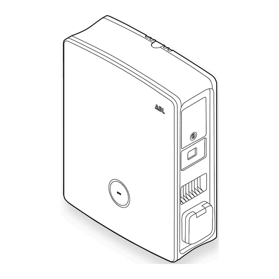
Introduction to the Wallbox eM4 Twin The Wallbox eM4 Twin at a glance The Wallbox eM4 Twin is designed as follows: Front and rear view The following illustration shows the Wallbox eM4 Twin from the front and from behind. Front Rear Suspension points There are two suspension points on the upper edge of the rear side, which are used to hang the eM4 Twin in the mounting rail which is screwed to the mounting position (see "Preparing and fixing the wallbox in place"... - Page 11 To ensure the compatibility of the RFID transponder, it should be tested with the Wallbox eM4 Twin. Besides the RFID standard used, other factors such as the dimensions of the transponder also influence compatibility. If you need support with testing an RFID transponder, contact ABL Customer Service (see "Contact" on page II). Interior and side view The following illustration shows the Wallbox eM4 Twin with the housing cover open and from the right-hand side:...
- Page 12 It also includes the RFID reader module for authorising the charging processes, provided that the wallbox was configured accordingly during installation or is operated with a backend. The RFID function is set up via the ABL Configuration App (see "Configuring the Wallbox eM4 Twin" on page 38).
-
Page 13: How The Hmi Works
The LEDs light up green, blue, white and red for 5 seconds. Configuration required If the wallbox has not yet been set up via the ABL Con- figuration App during first use or if the setup is cur- rently being performed, the LED circle pulsates white. - Page 14 Introduction to the Wallbox eM4 Twin Charging process active After a request by the vehicle, the charging operation in process is displayed dynamically via the blue status in- dicator for the charge point. The right half of the status indicator is assigned to the right-hand charge point, the left half to the left-hand charge point.
-
Page 15: Information Displayed In The Energy Meter
Information displayed in the energy meter Information displayed in the energy meter Each charge point of the Wallbox eM4 Twin has its own energy meter that shows various information about the charging operation via the three display lines. In contrast to the top line, the values displayed in lines 2 and 3 are switched cyclically: Total electric energy consumed The top line always shows the total electric power con-... -
Page 16: Forming Charging Groups And Network Topologies
Introduction to the Wallbox eM4 Twin Forming charging groups and network topologies The Wallbox eM4 Twin offers several interfaces for internal communication in a charging group as well as for exter- nal communication with a backend. Here, a distinction is made depending on the wallbox variant: ƒ... - Page 17 ƒ The wiring of the Wallbox eM4 Twin via LAN is described in the sections "Inserting the power and data cables" on page 26 and "Data cable connections" on page 33. ƒ Communication via LAN must be set up in the ABL Configuration App (see page 38 onwards). Communication in a charging group via LAN ƒ...
- Page 18 ƒ In the reev ready variants, the SIM card for communication with the reev backend is already pre-installed in the LTE USB stick in the Controller. ƒ LTE communication with the backend must be set up in the ABL Configuration App (see page 38 onwards). Communication with a backend via LTE ƒ...
-
Page 19: External Load Shedding In Accordance With Vde Ar-N 4100
External load shedding in accordance with VDE AR-N 4100 NOTE Compatibility with backend providers The Wallbox eM4 Twin is available as a reev ready product, which is specially prepared for operation with the backend solutions from reev. For more information, please visit: https://reev.com ƒ Alternatively, the Wallbox eM4 Twin is also compatible with other backends for managing the charging infra- structure. -
Page 20: Accessories
Albert-Büttner-Straße 11 D-91207 Lauf / Pegnitz Tel. +49 (0) 9123 188-0 Fax +49 (0) 9123 188-188 info@abl.de www.ablmobility.de ƒ Folding ferrite with key, 1 pc. The Controller variants of the eM4 Twin also include: ƒ LTE USB stick for installing an option- ally available SIM card for communi- cation with a backend, 1 pc. - Page 21 = 88 mm, w = 70 mm, d = 65 mm ƒ 100000253 RFID key fobs in ABL design for all ABL charging stations, 5 pcs. ƒ 100000192 POLEM4 Twin galvanised sheet metal mounting pole for the outdoor installation of one Wallbox eMH3 or eM4 Twin, the weather shield WPR36, and up to two...
- Page 22 Pack of 10 individual locks with the same closure, without group key, 10 pcs. ƒ 100000224, [...], 100000230 Pack of 10 individual locks with different closures, with one group key, 7 pcs. You can find further information on ABL charging stations and accessories at www.ablmobility.de/en.
-
Page 23: Installation Of The Wallbox Em4 Twin
Installation site requirements Installation of the Wallbox eM4 Twin The entire installation of the Wallbox eM4 Twin must be carried out by a qualified specialist electrical contractor. DANGER! Dangerous electrical currents Electrical installation, as well as final testing and certification for operation must be carried out by a qualified specialist electrical contractor, who, on the basis of their specialist training and experience, as well as their knowledge of the relevant standards, is able to assess and carry out the working steps described in this manual and recognise potential hazards. -
Page 24: Tools And Accessories Required
230 / 400 V EXT. CONTROL 130 mm 130 mm 230 / 400 V DATA EXT. CONTROL Albert-Büttner-Straße 11 D-91207 Lauf / Pegnitz Tel. +49 (0) 9123 188-0 Fax +49 (0) 9123 188-188 info@abl.de www.ablmobility.de ƒ Folding ferrite with key, 1 pc. - Page 25 Tools and accessories required If you want to operate your Controller wallbox or a group installation with a backend, you will need the following components: ƒ LTE USB stick included with the ƒ SIM card of the backend operator, Controller wallbox, 1 pc. 1 pc.
-
Page 26: Inserting The Power And Data Cables
Installation of the Wallbox eM4 Twin NOTE Network connection If you want to operate the Wallbox eM4 Twin wirelessly or wired in a network, you will also need suitable net- work components. Inserting the power and data cables The Wallbox eM4 Twin offers the option of inserting the supply cables from above, from below or directly through the rear wall via the supply cable area of the housing. -
Page 27: Preparing The Installation Site
Preparing the installation site Pre-stamped inlets in the housing edge The housing features pre-stamped inlets in the middle of the upper and lower edge, which can be opened with uni- versal pliers or a similar tool and are used for inserting the power and data cable. Decide before carrying out the installation how the pow- er and data cables should be fed into the wallbox. - Page 28 Installation of the Wallbox eM4 Twin NOTE Recommended cable lengths for wiring in the wallbox ABL recommends the following cable lengths to ensure problem-free connection in the wallbox: ƒ Power line: at least 130 mm ƒ Data cable: at least 170 mm ƒ Control cable: at least 130 mm Using the spirit level, align the drilling template lev- el and plumb on the mounting surface.
-
Page 29: Preparing And Fixing The Wallbox In Place
Preparing and fixing the wallbox in place Preparing and fixing the wallbox in place Continue to prepare the wallbox: Unlock both the side RCCB flaps using the key sup- plied and flip them up to unlock the housing cover. Grasp the upper edge of the housing cover with your fingertips and open the housing cover to the front. -
Page 30: Electrical Connection Of The Wallbox
Installation of the Wallbox eM4 Twin Fix the wallbox in place with the remaining screws supplied. • Screw the two TX30 half-round head screws through the upper attachment points in the mounting rail. • Screw the two TX30 wafer head screws into the wall via the lower attachment points. -
Page 31: Phase Rotation Within A Charging Group
Phase rotation within a charging group WARNING! Checking the connection Please ensure that the conductors that are pre-fixed to the terminals remain attached correctly after connecting the power supply cable. DANGER! Dangerous electrical currents The electronic components of your wallbox will be damaged if a voltage above 250 V is applied between the L1 current-carrying conductor and neutral! Phase rotation within a charging group To avoid a phase imbalance in a charging group, the phase rotation must be adjusted according to the following dia-... -
Page 32: Conversion From 3- To 1-Phase Operation Of The Wallbox Em4 Twin
Installation of the Wallbox eM4 Twin Conversion from 3- to 1-phase operation of the Wallbox eM4 Twin The Wallbox eM4 Twin is prepared for three-phase charging ex works. If required, however, it can also be converted to single-phase operation. The following working steps are also available as a video: Click here to watch the video. DANGER! Dangerous electrical currents ƒ... -
Page 33: Data Cable Connections
The charge points of the Wallbox eM4 Twin are now electrically set up for single-phase operation. In addition to the electrical conversion, however, you must also set up the wallbox for 1-phase operation via the ABL Configuration App. To do this, please refer to the sections starting on page 42. -
Page 34: Connecting A Control Cable In Accordance With Vde Ar-N 4100
The SIM card is provided by the backend provider and must first be inserted in the LTE USB stick. Then plug the LTE USB stick into the USB interface of the Controller and set up the communication via the ABL Configura- tion App (see page 43 onwards). -
Page 35: Wallbox Em4 Twin Start-Up
Wallbox eM4 Twin start-up Proceed as follows to prepare for communication with the backend via LTE: Open the LTE USB stick supplied by removing the cover. Insert the SIM card of the backend provider in the LTE USB stick and close the cover. Insert the LTE USB stick into the USB socket of the communication module in the Wallbox eM4 Twin. - Page 36 Installation of the Wallbox eM4 Twin Switch on the MCB for the wallbox in the domestic power distribution box. • During the boot phase, the LEDs of the status indicator will light up green, red, white and blue. • The status indicator will then pulsate dynami- cally in white: This means the wallbox is waiting to be configured by a qualified specialist elec- trical contractor (see "Configuring the Wallbox...
- Page 37 Carrying out all necessary tests for start-up After setting up via the ABL Configuration App, you must carry out all the tests prescribed for the installation site on the wallbox and the electrical installation to complete the start-up. These include the following tests: ƒ...
-
Page 38: Configuring The Wallbox Em4 Twin
ƒ Updating the software of the charging station, etc. Availability of the ABL Configuration App The ABL Configuration App is offered as an app for mobile devices such as smartphones and tablets. You can download the app for the following operating systems on a mobile device:... - Page 39 Accepting the Terms and Conditions and Privacy Policy When opening the ABL Configuration App for the first time, after reinstalling the app or when ABL makes changes to the stored documents, you must agree to the ABL Terms and Conditions and Privacy Policy on this screen.
- Page 40 On iOS 13 / iPadOS 13 and later versions, data for wireless communication can only be accessed if you allow the ABL Configuration App to use Location Services on the mobile device. This is a technical policy from Apple, but the location data will not be used by ABL in the app or shared with third parties.
- Page 41 Setting up communication via the ABL Configuration App After the connection has been successfully estab- lished, the wallbox is displayed along with its serial number and the status Connected. J Tap Continue to protect your wallbox from unau- thorised access using a custom password.
-
Page 42: Onboarding - Configuration Of An Extender Wallbox For Stand-Alone Operation
Configuration of the wallbox by a qualified specialist electrical contractor Before you can start configuring the wallbox, the ABL Configuration App displays a safety warning: The inter- nal parameters of the wallbox may only be changed by qualified specialist electrical contractors. -
Page 43: Onboarding - Configuring The Controller / Extender Operating Mode
If you selected the Controller / Extender option when selecting the operating mode (see step 4 in the section "Set- ting up communication via the ABL Configuration App"), you must set up the parameters below for all charge points within the group after entering the password to protect the wallbox. -
Page 44: Control Board Settings And Reboarding
Control Board settings and reboarding To complete the configuration of the selected operating mode, you can switch to the Control Board of the ABL Configuration App on the last screen. Here you can check all the settings you have made so far and change them if necessary, as well as set up further parameters for operation. -
Page 45: Description Of The Charging Process
Description of the charging process After setting up via the ABL Configuration App, the setup is complete and the Wallbox eM4 Twin is ready for charging. We recommend carrying out an initial charging process with a vehicle during start-up to ensure the func- tionality of the wallbox. - Page 46 Description of the charging process Check the status indicator of the wallbox (Display: 1 cycle). • If the charging operation has to be enabled using an RFID card, a blue chase light is shown dynami- cally on the status indicator. »...
- Page 47 Control Board settings and reboarding WARNING! RFID card not readable If the antenna of your RFID card is blocked or damaged, the card cannot be recognised. ƒ Remove the RFID card from its protective cover or card holder to register at the RFID reader. ƒ...
-
Page 48: Error Resolution And Maintenance
In addition, components may be damaged and must then be repaired or replaced if necessary. Support via the ABL Support page If any problems occur, you can get help quickly and easily via the Support area on the ABL website. Visit the following web address: https://www.ablmobility.de/en/service/support/... -
Page 49: Quick Solution For General Problems
Quick solution for general problems In the event of a problem, you do not need to contact ABL Support immediately, as in most cases there is a simple solution. You should therefore always check the following points first before generating a ticket. -
Page 50: Testing The Rccb
Repeat this process for the second RCCB. DANGER! Dangerous electrical currents Should an RCCB malfunction during testing, you must not continue to operate the wallbox under any circumstances! ƒ Take the wallbox out of operation (see next section) and contact ABL Customer Service (see "Contact" on page II). -
Page 51: Taking The Wallbox Em4 Twin Out Of Operation
Taking the Wallbox eM4 Twin out of operation Taking the Wallbox eM4 Twin out of operation In case of severe malfunctions or damage to the device, you must take the Wallbox eM4 Twin out of operation. To do so, proceed as follows: Open your domestic power distribution box, discon- nect the power supply cable from the electricity grid via the MCB, secure the MCB against being switched on again and close the distribution box. -
Page 52: Replacing The Rccb Flap
To order spare parts, you will need to create a support ticket in the Service > Support > Spare parts section of the ABL website (see "Support via the ABL Support page" on page 48). Proceed as follows to replace an RCCB flap on the Wallbox eM4 Twin:... -
Page 53: Replacing The Lever Lock In An Rccb Flap
NOTE Changing the lock system ABL offers different types of locks for the Wallbox eM4 Twin, which can be ordered as accessories (see "Acces- sories" on page 20). ƒ Locking circuit A: In locking circuit A there are 10 packages to choose from, each with 10 individual locks with the same closure. - Page 54 Error resolution and maintenance Move the locking cylinder to the locked position (tongue pointing downwards) and remove the key. Place the RCCB flap on the front. Loosen the screw for the locking cylinder with a Torx T15 screwdriver. Remove the bracket for the lock with the slotted screwdriver.
-
Page 55: Replacing The Charging Socket Flap
Replacing the charging socket flap Replacing the charging socket flap You can replace the flaps of the Type 2 charging sockets if they are damaged or no longer close reliably. Specialist electrical End customer contractor Construction Required components: Number / spare part 100000261 / Spare part eM4 charging socket flap Accessories –... -
Page 56: Replacing The Housing Cover
Specialist electrical End customer contractor Construction Required components: Number / spare part 100000259 / Spare part eM4 TW front ABL Accessories Key for RCCB flap, supplied with the wallbox Tool – Proceed as follows to replace the wallbox housing cover: Unlock both the side RCCB flaps using the key sup- plied and flip them up to unlock the housing cover. -
Page 57: Resetting The Wallbox And Restoring To Factory Settings
Accessing the help system on an Extender wallbox If you tap the button while the ABL Configuration App is connected to an Extender wallbox, you will be redi- rected directly to ABL’s support website. Resetting or restoring the wallbox via the reset pushbutton There is a reset pushbutton on the main module of the wallbox which you can use to restart the hardware or reset the wallbox to its factory settings, depending on how long you press the button. -
Page 58: Measures For Handling Errors And Warnings
Error resolution and maintenance Proceed as follows to trigger the reset pushbutton on the Wallbox eM4 Twin: Unlock both the side RCCB flaps using the key sup- plied and flip them up to unlock the housing cover. Open the housing cover to the front. Locate the reset pushbutton, which is set back on the main module of the wallbox. - Page 59 Visualisation example Description Every malfunction and warning is documented in detail in the app. In addition to a reference to the ABL Configuration App affected charge point, the app provides access to a diagnostic report and troubleshooting instructions. WARNING! Checking the internal RCCB of the wallbox If the status indicator of the HMI flashes red but no display is shown in one or both energy meter windows, check the internal RCCB of the wallbox and move it to the position I if necessary.
- Page 60 ƒ Perform restart by pressing reset push button Internal communication Charging not possible error (< 3 seconds) ƒ Update the wallbox’s software using the ABL [...] Update error Charging still possible Configuration App ƒ Perform restart by pressing reset push button...
-
Page 61: Maintenance
(2) minutes via the MCB connected upstream in the domestic power distribution. ƒ If the error or warning still cannot be remedied or reset even after doing this, contact ABL Customer Service (see "Contact" on page II). -
Page 62: Appendix
Appendix Appendix Technical specifications eM4 Twin Controller series Product number 100000002 Rated voltage 230/400 V Rated frequency 50 Hz Rated current 32 A Maximum output 2 × 11 kW or 1 × 22 kW Connection system Type 2 charging socket, 2 pcs. Phase system 3-phase (reconfigurable to 1-phase) Direct connection to the terminal block, supply cables up Terminal blocks to a maximum of 10 mm²... - Page 63 Technical specifications Product number 100000002 Power dissipation 8 W Maximum elevation ≤ 2,000 m AMSL Dimensions (H × W × D) 515 × 428 × 145 mm (width without overhangs: 395 mm) Weight per wallbox Approx. 10.5 kg The Wallbox eM4 Twin Controller is also available as a variant with a shutter charging socket. In addition, all variants of the Wallbox eM4 Twin Controller are available as reev ready variants, which are ready for operation with the back- end solutions from reev.
-
Page 64: Standards And Guidelines
Appendix Product number 100000004 Operating temperature -25°C to 40°C Storage temperature -25°C to 70°C Relative humidity 5 to 95%, no condensation Class of protection Degree of protection (housing) IP55 Overvoltage category Degree of pollution Impact strength IK10 Power dissipation 7 W Maximum elevation ≤... -
Page 65: Trademarks
Trademarks Trademarks All trademarks mentioned in this manual, including those that may be protected by third parties are, without restric- tion, subject to the regulations of the respectively applicable trademark law and the property rights of the respective registered owners. All trademarks, trading names or company names marked here as such are, or may be, trademarks or registered trademarks of their respective owners. -
Page 66: Copyright And Disclaimer
Appendix Copyright and disclaimer Copyright © 2023 Version 0301501_EN_a, Version: 26.04.23 All rights reserved. ƒ Any information contained in this manual may be changed without prior notice and does not represent any obliga- tion on the part of the manufacturer. ƒ... -
Page 67: Ce Certification And Compliance Declaration
The Wallbox eM4 Twin carries the CE mark. A copy of the declaration of compliance is displayed be- low. In addition, you can find a digital copy of the declaration of conformity on the ABL website at www.ablmobility.de/en in the section Service > All downloads > Compliance declarations. -
Page 68: Drilling Template Illustration
The Wallbox eM4 Twin comes with a drilling template (see illustration below) for marking the mounting points and illustrates the basic steps for installation. Should the supplied drilling template have been lost, you can obtain the drilling dimensions from the illustration on the front. Wallbox eM4 Twin 230 / 400 V DATA EXT. - Page 69 L3 L1 L1 L2 L3 N L3 L1 N L3 L1 L2 N eM4 Twin L1 L2 L3 L1 L2 #10 eM4 Twin L1 L2 L3 L1 L2 L3 … Revisionsstand 100000171_Index_B, 04/23 ABL GmbH Albert-Büttner-Straße 11 D-91207 Lauf / Pegnitz ...
- Page 70 ABL GmbH Albert-Büttner-Straße 11 91207 Lauf an der Pegnitz Germany +49 (0) 9123 188-0 +49 (0) 9123 188-188 info@abl.de www.ablmobility.de...
Need help?
Do you have a question about the eM4 Twin and is the answer not in the manual?
Questions and answers