Advertisement
Quick Links
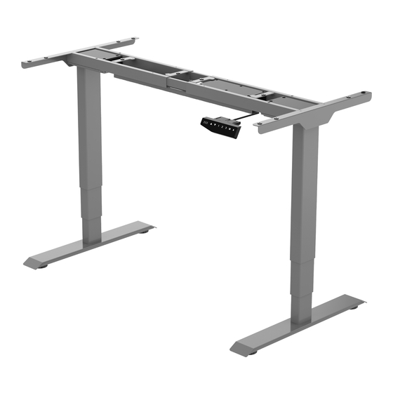
Item No.:75.BUR.001
Installation guide
Technical data
3 stage
100-240V
Column stage
Input Voltage
125KG
Max Speed
38mm
Max Loading capacity
Height range
620-1250mm
Temperature
0-40°C
C E F CC CUL
Length range
1100-1800mm
Certification
10%(continuous operation for 2 mins at most after pause for 18 mins)
Duty cycle
Component list
No.
Part
Qty
No.
Part
Qty
1
2
2
2
Pedestal
Lifting Column
No.
Qty
No.
Part
Qty
3
1
4
2
Supporting beam
Cable management
No.
Qty
No.
Part
Qty
5
2
6
1
Supporting plate
Control box
No.
Qty
No.
Part
Qty
Handswitch
7
1
8
1
Power cable
Accessory list
Attention: The drawings below are only for reference which might be
slightly different from the actual object, please in kind prevail. Any
tools missing or installation problems, please contact the customer
service firstly.
No.
Image
Spec
A
M6×16mm
B
ST4.2x20mm
C
M8×35mm
/
s
D
Square spacer
Wrench
E
4x4mm
6
8
5
3
4
2
1
STEP 1
C
E
x4
E
5x5
Qty
8
26
安装步骤2
STEP 2
8
C
6
x4
1 per
Wrench
5x5mm
wrench
E
5
5x5
5
STEP 3
7
A
x8
E
2
1
4x4
C
3
2
E
3
C
E
A
2
Install (2) & (3) together, use 5*5 wrench(E)
to tighten the screws(C).
Install (5) & (3) together, use 5*5 wrench(E)
to tighten the screws(C).
Install (2) & (1) together, use 4*4 wrench(E)
to tighten the screws(A).
Advertisement

Related Manuals for Euroseats 75.BUR.001


Summary of Contents for Euroseats 75.BUR.001
- Page 1 STEP 1 Item No.:75.BUR.001 Install (2) & (3) together, use 5*5 wrench(E) to tighten the screws(C). Installation guide Accessory list Attention: The drawings below are only for reference which might be slightly different from the actual object, please in kind prevail. Any tools missing or installation problems, please contact the customer service firstly.
- Page 2 STEP 4 Unscrew the screws Slide the supporting Install the handswitch(7) beam onto the table Put the Square spacer onto the square tube Tighten the screws tabletop STEP 5 Connect all the cables onto the control box(6) Power port Port for cable Port for connected to the hand switch...
Need help?
Do you have a question about the 75.BUR.001 and is the answer not in the manual?
Questions and answers