Sign In
Upload
Download
Add to my manuals
Delete from my manuals
Share
URL of this page:
HTML Link:
Bookmark this page
Add
Manual will be automatically added to "My Manuals"
Print this page
×
Bookmark added
×
Added to my manuals
Manuals
Brands
Kenwood Manuals
Power Supply
PR18-1.2
Instruction manual
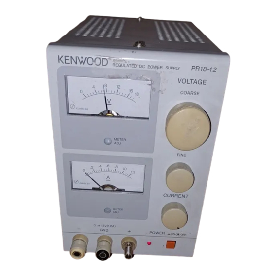
Kenwood PR18-1.2 Instruction Manual
Regurated dc power supply
Hide thumbs
1
2
3
4
5
6
7
8
9
10
11
12
13
14
page
of
14
Go
/
14
Troubleshooting
Bookmarks
Advertisement
Quick Links
Download this manual
R E G U R A T E D D C P O W E R S U P P L Y
PR18-1.2 PR36-1.2
PR18-3 PR36-3
PR18-5
INSTRUCTION MANUAL
K E N W O O D C O R P O R A T I O N
©PRINTED IN JArAN B63-0018-08 91/12 11 10 9 8 7 6 5 4 3 2 1 90/12 11 10 * 6 7 6 5 4
PR70-1
Table of
Contents
Previous
Page
Next
Page
1
2
3
4
5
Advertisement
Need help?
Do you have a question about the PR18-1.2 and is the answer not in the manual?
Ask a question
Questions and answers
Related Manuals for Kenwood PR18-1.2
Power Supply Kenwood PR18-1.2A Brochure & Specs
Regulated dc power supplies pr-a series (4 pages)
Power Supply Kenwood PR-A Series Instruction Manual
Regulated dc power supply (17 pages)
Power Supply Kenwood PR-657 Instruction Manual
(20 pages)
Power Supply Kenwood PR36-1.2 Instruction Manual
Regurated dc power supply (14 pages)
Power Supply Kenwood PR18-3 Instruction Manual
Regurated dc power supply (14 pages)
Power Supply Kenwood PR36-3 Instruction Manual
Regurated dc power supply (14 pages)
Power Supply Kenwood PR18-5 Instruction Manual
Regurated dc power supply (14 pages)
Power Supply Kenwood PR70-1 Instruction Manual
Regurated dc power supply (14 pages)
Power Supply Kenwood PS Series Instruction Manual
Regulated dc power supply (58 pages)
Power Supply Kenwood PS-33 Instruction Manual
Dc power supply (10 pages)
Power Supply Kenwood PS-33 Instruction Manual
(10 pages)
Power Supply Kenwood PS-31 Instruction Manual
(7 pages)
Power Supply Kenwood PS-31 Instruction Manual
(10 pages)
Power Supply Kenwood PA18-1.2 Instruction Manual
(34 pages)
Power Supply Kenwood PWR18-2 Instruction Manual
Regulated dc power supply (32 pages)
Power Supply Kenwood PD18-10 Instruction Manual
Regulated dc power supply (28 pages)
This manual is also suitable for:
Pr36-1.2
Pr18-3
Pr36-3
Pr18-5
Pr70-1
Print
Rename the bookmark
Delete bookmark?
Delete from my manuals?
Login
Sign In
OR
Sign in with Facebook
Sign in with Google
Upload manual
Upload from disk
Upload from URL


Need help?
Do you have a question about the PR18-1.2 and is the answer not in the manual?
Questions and answers