
Related Manuals for Kenwood PR-A Series


Summary of Contents for Kenwood PR-A Series
- Page 1 REGULATED DC POWER SUPPLY PR-A SERIES PR18-1.2A PR18-3A PR18-5A PR36-1.2A PR36-3A PR70-1A PR250-0.42A INSTRUCTION MANUAL KENWOOD CORPORATION CO PRINTED IN JAPAN B63-0174-00(N) 36505...
-
Page 2: Table Of Contents
CONTENTS 1. OUTLINE • 2. FEATURES • • • 4 3. SPECIFICATIONS 4. PRECAUTIONS FOR USE 5. EXPLANATION OF PANELS 5-1. FRONT PANEL • 5- 2. REAR PANEL 6. OPERATION PROCEDURES ••• • •••• 6- 1. STAND-ALONE OPERATION • 6-2. OPERATION IN SERIES ••••... -
Page 3: Outline
1. OUTLINE The PR-A Series i s a s e r i a l control type regulted DC power supply. I t i s a constant voltage/current power supply whose output can be varied from 0 up to the rated values. -
Page 4: Specifications
3. SPECIFICATIONS I t e m PR18-1.2A PR18 3A PR18-5A PR36-L 2A PR36-3A PR70-1A PR250-0.42A Output voltage (continuosly variable, coarse 0 to 18V 0 to 36V 0 to 70V 0 to 250V and fine adusts) Output current (continuosly variable) 0 to 1.2A 0 to 3A 0 to 5A 0 to 1.2A... - Page 5 PR18-3A I t e m PR18-1.2A PR18-5A PR36-L 2A PR36-3A PR70-1A PR250-0.42A Funct i ons Output on/off switching Turn the output on and off. Serial connection (independent control mode) Can be connected in series (within limits of ground proof voltage.) Parallel operation (master-slave mode) Can be operated in "one-control"...
-
Page 6: Precautions For Use
PRECAUTIONS FOR USE 1) Confirming the supply voltage *Use t h i s unit w i t h i n the s p e c i f i e d range. The unit's rated voltage i s single-phase 100/120/200/220/240VAC ±10X (max. 250V) at 50/60Hz. *The rated voltage i s indicated on the specification and name plate located beside the input connector on the rear panel. -
Page 7: Explanation Of Panels
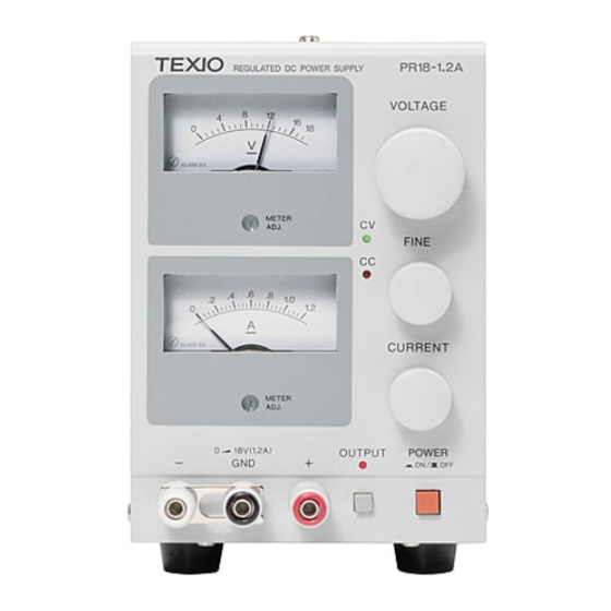
5, EXPLANATION OF PANELS •igure Figure 2. -
Page 8: Front Panel
Front panel ©POWER O N • /OFF • The power switch, The power supply should be on and operating when this switch i s depressed. ©OUTPUT switch Turns the output on and off. When the output i s turned on, the OUTPUT LED goes on. ©Voltmeter A DC voltmeter that indicates the output voltage. -
Page 9: Rear Panel
5-2, Rear panel ®MASTER/SLAVE switch Used during "one-contro 1" p a r a l l e l o p e r a t i o n i n the m a s t e r / s l a v e configuration. -
Page 10: Operation Procedures
6. OPERATION PROCEDURES 6-1. Stand-alone operation *When using the power supply in stand-alone, simply operate by manipulation of the panel switches as needed. However, be sure that the MASTER/SLAVE switch i s set to MASTER. 6-2, Serial connection Two or more u n i t s of the power supply can be hooked up i n s e r i e s to achieve in increase in output voltage. -
Page 11: Operation In Parallel
Parallel operation (master-slave control) *Two or more units of the same machine can be hooked up in parallel to give an increase in output current. The total output current w i l l be the sum of the output currents of the individual machines. * In p a r a l l e l operation, one machine wi11 act as the masster and a l l others wi 11 act as slaves. - Page 12 Hook-up front panel terminals in the parallei operation mode. Slave 1 Slave 2 Note; I = I i + I + Is in constant voltage mode and The voltage presets on a l l the s l a v e m a c h i n e s a r e s e t to the slaves opeate i n constant maximum, The master operates current mode.
-
Page 13: Maintenance
MA INTENANCE 7-1. Removing the case The case can be removed by taking out the screws on the top and side panels and pulling the case upwards. Screws Figure 8. 7-2. Changing the rated source voltage To change the AC source voltage of the machine, change the internal power transformer and fuse specifications as shown in the figure below. -
Page 14: Fuse Replacement
7-3 Fuse replacement When a fuse blows, replace i t after investigating the cause of the blow-out. Furthermore, since a l t e r a t i o n s of the supply voltage i s accompanied by a change in fuse type, select a fuse that has the appropriate rating according to the chart below. -
Page 15: Troubleshooting
TROUBLESHOOTING P r o b l e m Indicators or Areas to check C a u s e power supply w i l l Power ON lamp does not light *poor connection of not go on. power cord, or broken wire *Bad power switch *Fuse meltdown... - Page 16 A p r o d u c t o f KENWOOD CORPORATION 2-5, 1 -chome Shibuya, Shibuya-ku, Tokyo 150, Japan...
- Page 17 Change to Instruction Manual of PR-A Power Supply S e r i e s Please change the following descriptions to the i n s t r u c t i o n manual of PR-A power supply s e r i e s . (Page E R R O R S P E C...
Need help?
Do you have a question about the PR-A Series and is the answer not in the manual?
Questions and answers