
Related Manuals for Jain Technology XONIC 100L


Summary of Contents for Jain Technology XONIC 100L
- Page 1 Industrial & Defense Instruments ® 100L ONIC LTRASONIC RANSIT LOWMETER IQUID User Manual 2021 www.jain.co.kr Tel. 82-2-856-4114 Fax. 82-2-856-9503...
-
Page 2: Table Of Contents
Xonic 100L, 2021 Table of Contents Delivery Items Preview Introduction Safety Consideration Installation Steps Specifications Key Functions Understanding Display Best Transducer Installation Place Section 1. General SYSTEM LOCK SITE NAME APPLICATION FLANGE SET Section 2. CH SELECT Section 3. PIPE Data Section 4. -
Page 3: Delivery Items
Xonic 100L, 2021 Delivery Items Flow Computer Transducer Sensor cable, Mounting Track... -
Page 4: Preview
Safety Consideration Xonic 100L uses external power of AC110~220V . Follow all electrical and electronic safety rules to prevent any safety accident or damage of the flow computer during installation. Most applications are near to moisture, thus, be careful of any electric shock. -
Page 5: Key Functions
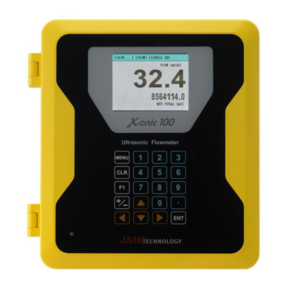
Xonic 100L, 2021 Key Functions Note : Touch keys do not have alphabet table, so user must select alphabet by pressing DIRECTION KEYS. Keys Functions Press to enter the menu or back to the main display. Press to enter the selected menu or save the input data. -
Page 6: Understanding Display
Xonic 100L, 2021 Understanding Display SITE NAME : site name inputted by user. For example, SINGLE CH means single path/channel. FLOW UNIT : flow unit selected by user. FLOW : measured flow TOTAL : total flow TOTAL UNIT : total flow unit... -
Page 7: System Lock
Xonic 100L, 2021 Section 1. input GENERAL data System Lock User can set password to prevent unauthorized access to the flow computer. Input number and alphabet using keypad. MAIN MENU GENERAL CH SELECT PIPE LIQUID INSTALL OPERATE GENERAL FLOW 1 . SYSTEM LOCK IN/OUTPUT 2 . -
Page 8: Section 2. Ch Select
Xonic 100L, 2021 Section 2. CH SELECT User should select channel first to setup the data in other menus. In case of single channel, select CHANNEL 1. In case of dual channel, user have to setup the data of each channel separately. -
Page 9: Section 3. Pipe Data
Xonic 100L, 2021 Section 3. Input PIPE Data Pipe Unit Select pipe unit: METRIC or US units (inch) MAIN MENU GENERAL CH SELECT PIPE PIPE 1 . PIPE UNIT LIQUID 2 . PIPE MATERIAL INSTALL 3 . PIPE SONIC Vs OPERATE 4 . - Page 10 Xonic 100L, 2021 Lining Material If pipe has lining, select lining material. LINING MATERIAL 1 . NONE PIPE 2 . MORTAR 1 . PIPE UNIT 3 . TAR_EPOXY 2 . PIPE MATERIAL 4 . TEFLON 3 . PIPE SONIC Vs 5 .
-
Page 11: Section 4. Liquid Type
Xonic 100L, 2021 Section 4. Select LIQUID TYPE User can select liquid type from list. Sonic velocity, viscosity and density are automatically selected by flowmeter. If liquid type is unknown, user must input 3.VISCOSITY and 4.DENSITY manually. Liquid Material Select liquid type from Material list. -
Page 12: Section 5. Install
Xonic 100L, 2021 Section 5. INSTALL For proper installation, please read this section carefully. After input pipe and liquid data, user can install quickly and easily. Sensor Type User must have correct transducer for the pipe. Xonic 100 has 5 types of transducers and Xonic 100 will automatically recommend proper transducers for the site. - Page 13 Xonic 100L, 2021 <V mode installation> If pipe is large in diameter (over 1000mm) or very old (scale or corrosion inside), please use Z MODE installation. These pipes can sometimes make the ultrasonic signal very weak, so flowmeter cannot work in V mode. Also, in the case that liquid is not clean, for example wastewater, please use Z MODE.
- Page 14 Xonic 100L, 2021 Finding Installation Position Please find enough straight run pipe position. Normally, clamp-on ultrasonic flowmeter need 10 Upstream and 5 Downstream diameters straight pipe run. Ensure adequate straight pipe to ensure smooth laminar flow. Accuracy will be affected if not enough straight pipe can be found.
- Page 15 Xonic 100L, 2021 Install Mounting Track Install mounting track onto the pipe with stainless steel strap. Fix it tightly. 센서고정용트랙 Easy Mounting Track Space 센서의 설치거리 트랙고정용 스트랩 Strap Kit Install Transducers Apply couplant gel onto bottom of transducers and locate transducer into onto PIPE mounting track.
- Page 16 Xonic 100L, 2021 After auto installation, Xonic 100 shows the below ultrasonic signals. The signal shape must be like the below picture. Time Difference Measured Flow Gain Level Perfect Ultrasonic Signal Measured Sound Speed Sound Vs : In case of water 20°C, the sound speed must be around 1480 m/s.
- Page 17 Xonic 100L, 2021 Section 6. OPERATION Upper Flow Limit This menu means the site flow cannot exceed flow limitation. MAIN MENU OPERATE GENERAL 1 . UPPER FLOW LIMIT CH SELECT 2 . LOWER FLOW LIMIT PIPE 3 . DEAD ZONE LIQUID 4 .
- Page 18 Xonic 100L, 2021 OPERATE 1 . UPPER FLOW LIMIT 2 . LOWER FLOW LIMIT 3 . DEAD ZONE 4 . FLOW AVERAGE TIME 5 . TOTAL FLOW SET 6 . ALARM 7 . CALIBRATION 8 . ENABLE AGC FLOW AVERAGE TIME 9 .
- Page 19 Xonic 100L, 2021 Move cursor to CALIBRATION METHOD. 1) NO CALIBRATION is no calibration. It does not affect any calibration to the flow. 2) MULTI-POINTS is multi-point calibration menu. User can test flow from minimum to max flow. And can input each test points to flowmeter.
- Page 20 Xonic 100L, 2021 OPERATE 1 . UPPER FLOW LIMIT 2 . LOWER FLOW LIMIT 3 . DEAD ZONE 4 . FLOW AVERAGE TIME 5 . TOTAL FLOW SET 6 . ALARM 7 . CALIBRATION 8 . ENABLE AGC ENABLE AGC 9 .
-
Page 21: Section 7. Flow
Xonic 100L, 2021 Section 7. FLOW Flow Volume Unit User can select any unit from list. MAIN MENU GENERAL FLOW CH SELECT 1 . FLOW VOLUME UNIT PIPE 2 . FLOW TIME UNIT LIQUID 3 . FLOW RESOLUTION FLOW VOLUME UNIT INSTALL 4 . - Page 22 Xonic 100L, 2021 FLOW 1 . FLOW VOLUME UNIT 2 . FLOW TIME UNIT 3 . FLOW RESOLUTION 4 . FLOW SCALE 5 . TOTAL VOLUME UNIT 6 . TOTAL RESOLUTION 7 . TOTAL SCALE FLOW SCALE 8 . BATCH TOTAL 1 .
- Page 23 Xonic 100L, 2021 FLOW 1 . FLOW VOLUME UNIT 2 . FLOW TIME UNIT 3 . FLOW RESOLUTION 4 . FLOW SCALE 5 . TOTAL VOLUME UNIT 6 . TOTAL RESOLUTION 7 . TOTAL SCALE BATCH TOTAL 8 . BATCH TOTAL Vol Unit : m³...
-
Page 24: Section 8. In/Output
Xonic 100L, 2021 Section 8. IN / OUTPUT Analog Out [1] Xonic 100 has two analog output functions for 4-20mADC output. User can assign output data and set range. MAIN MENU GENERAL CH SELECT PIPE ANALOG OUT [1] LIQUID IN/OUTPUT 1 . - Page 25 Xonic 100L, 2021 ANALOG IN [1] IN/OUTPUT 1 . SET ENABLE 1 . ANALOG OUT [1] 2 . CALIBRATION_MIN 2 . ANALOG OUT [2] 3 . CALIBRATION_MAX 3 . RELAY OUT [1] 4 . MIN INPUT SPAN 4 . RELAY OUT [2] 5 .
-
Page 26: Section 9. Datalogger
Xonic 100L, 2021 Section 9. DATALOGGER The flowmeter provides both of RS-232C and RS-485 for the communication. Caution) Before user start logging data, user should review this section carefully. Time Set User must setup the correct date and time for recording the measurement. - Page 27 Xonic 100L, 2021 CONFIGURE 1 . BAUD RATE 2 . DATA BITS 3 . PARITY 4 . STOP BITS STOP BITS 5 . LINE FEED 1 . 1Bits 6 . NETWORK ID 2 . 2Bits Line Feed CONFIGURE 1 . BAUD RATE 2 .
- Page 28 Xonic 100L, 2021 RS-232C FORMAT 1 . CONFIGURE HFTA 2 . HEADER 3 . FORMAT H:Header 4 . SEPERATOR S:Site name 5 . LOG INTERVAL N:Channel No 6 . LOG TIME SYNC. D:Date, C:Time 7 . LOG ENABLE F:Flow , T:Total 8 .
- Page 29 Xonic 100L, 2021 RS-232C 1 . CONFIGURE 2 . HEADER 3 . FORMAT 4 . SEPERATOR 5 . LOG INTERVAL 6 . LOG TIME SYNC. 7 . LOG ENABLE 8 . COMM MODE LOG ENABLE 9 . SELECT COMM 1 . DISABLE 0 .
- Page 30 Xonic 100L, 2021 Memory of Datalogger Internal Memory User can see the records of First Log and Last Logger. Log Output MEMORY 1 . LOG OUTPUT 2 . FORMAT DATALOG 3 . LOG INTERVAL 1 . TIME SET MEMORY 4 . LOG TIME SYNC.
- Page 31 Xonic 100L, 2021 MEMORY 1 . LOG OUTPUT 2 . FORMAT 3 . LOG INTERVAL 4 . LOG TIME SYNC. 5 . LOG ENABLE LOG ENABLE 6 . PORT SELECT 1 . DISABLE 7 . MEMORY CLEAR 2 . ENABLE...
-
Page 32: Section 10. Diagnostics
Xonic 100L, 2021 Section 10. Diagnostics User can see what happen in flowmeter through diagnostic functions. MAIN MENU GENERAL CH SELECT PIPE LIQUID INSTALL DIAG OPERATE 1 . FREQUENCY DIV FLOW 2 . RISC IN/OUTPUT 3 . PULSE COUNT FREQUENCY DIV DATALOG 4 . - Page 33 Xonic 100L, 2021 DRAWINGS...
- Page 34 Xonic 100L, 2021...
- Page 35 Xonic 100L, 2021...
- Page 36 Xonic 100L, 2021...
- Page 37 Xonic 100L, 2021...
- Page 38 Xonic 100L, 2021...
- Page 39 Xonic 100L, 2021...
- Page 40 Xonic 100L, 2021...
- Page 41 Xonic 100L, 2021...
- Page 42 Xonic 100L, 2021 #710, 55, Digital-ro 33-gil, Guro-gu, Seoul, Korea TEL. 82-2-856–4114 FAX. 82-2-856–9503 www.jain.co.kr...
Need help?
Do you have a question about the XONIC 100L and is the answer not in the manual?
Questions and answers