Table of Contents
Advertisement
Quick Links
Advertisement
Table of Contents

Subscribe to Our Youtube Channel
Related Manuals for AirLive POE-GSH1816R-250


Summary of Contents for AirLive POE-GSH1816R-250
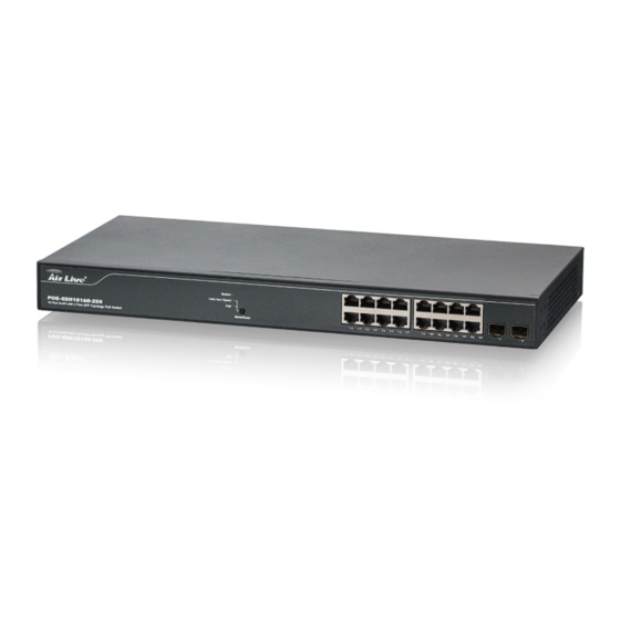
- Page 1 POE-GSH1816R-250 16 Port RJ45 with 2 Port SFP Topology POE Switch User Manual...
- Page 2 OvisLink Corp. has made the best effort to ensure the accuracy of the information in this user’s guide. However, we are not liable for the inaccuracies or errors in this guide. Please use with caution. All information is subject to change without notice All Trademarks are properties of their respective holders. AirLive POE-GSH1816R-250 User Manual...
-
Page 3: Table Of Contents
3.2 Prepare your PC .................. 9 3.3 Management Interface ................. 9 3.4 Introduction to Web Management ............10 4. Web Management: System of POE-GSH1816R-250 ......13 4.1 System ....................13 4.2 Port Management ................53 4.3 PoE Management ................73 4.4 VLAN Management ................ - Page 4 4.12 Access Control ................227 4.13 Event Notification ................230 4.14 Diagnostics ..................231 4.15 Maintenance .................. 236 5. Web Management: Device of POE-GSH1816R-250 ......246 5.1 Graphic Monitoring ................246 5.2 Management ..................251 5.3 Maintenance ..................253 6. Trouble Shooting ................... 257 6.1 Incorrect Connections ..............
-
Page 5: Introduction
Introduction 1.1 Overview The POE-GSH1816R-250 is a 16-port Gigabit TP L2 PoE switch with 2-Port Gigabit TP/SFP slots. This Switch can power on 802.3at/af cameras by RJ45 cable. Web-based management unit, associated with SNMP agent allow user access the switch remotely. In... -
Page 6: How To Use This Guide
1. Introduction 1.2 How to Use This Guide POE-GSH1816R-250 is a SNMP and web smart PoE Switch with many functions. It is recommended that you read through the entire user’s guide whenever possible. The user guide is divided into different chapters. You should read at least go through the first 2 chapters before attempting to install the device. -
Page 7: Installing The Poe-Gsh1816R-250
POE-GSH1816R-250. For software configuration, please go to chapter 3 for more details. 2.1 Before You Start It is important to read through this section before you install the POE-GSH1816R-250 The maximum cabling distance is 100 meters by Cat5e RJ45 cable. -
Page 8: Optional Accessory
2. Installing the POE-GSH1816R-250 Compare the contents of your POE-GSH1816R-250 package with the standard checklist above. If any item is missing or damaged, please contact your local dealer for service. 2.3 Optional Accessory The POE-GSH1816R-250 has the following optional accessories which you can purchase from AirLive ... -
Page 9: Knowing Your Poe-Gsh1816R-250
Below are descriptions and diagrams of the product: 2.5 Hardware Installation Set the POE-GSH1816R-250 on a sufficiently large flat space with a power outlet nearby. The surface where you put your POE-GSH1816R-250 should be clean, smooth, level and sturdy. Make sure there is enough clearance around the POE-GSH1816R-250 to allow attachment of cables, power cord and allow air circulation. - Page 10 2. Installing the POE-GSH1816R-250 2.5.2. Rack-mounted Installation The POE-GSH1816R-250 comes with a rack-mounted kid and can be mounted in an EIA standard size, 19-inch Rack. The POE-GSH1816R-250 can be placed in a wiring closet with other equipment. Perform the following steps to rack mount the POE-GSH1816R-250: Position one bracket to align with the holes on one side of the POE-GSH1816R-250 and secure it with the smaller bracket screws.
-
Page 11: Led Table
2.5.3. Power On Connect the power cord to the power socket on the rear panel of the POE-GSH1816R-250. The other side of power cord connects to the power outlet. The internal power supply of the POE-GSH1816R-250 works with voltage range of AC in the 100-240VAC, frequency 50~60Hz. - Page 12 2. Installing the POE-GSH1816R-250 Status Description System Green Power is ON Green On Link up 1000M Link/ACT/Speed Yellow On Link up 100M Blinking Data activating Green PoE device connecting AirLive POE-GSH1816R-250 User Manual...
-
Page 13: Introduce The Poe-Gsh1816R-250
The default password is airlive 3.2 Prepare your PC The POE-GSH1816R-250 can be managed remotely by a PC through RJ-45 cable. The default IP address of the POE-GSH1816R-250 is 192.168.2.1 with a subnet mask of 255.255.255.0. This means the IP address of the PC should be in the range of 192.168.2.2 to 192.168.2.253. -
Page 14: Introduction To Web Management
Web Management (HTTP): You can manage your POE-GSH1816R-250 by simply typing its IP address in the web browser. Most functions of POE-GSH1816R-250 can be accessed by web management inter face. We recommend using this interface for initial configurations. To begin, simply enter POE-GSH1816R-250’s IP address (default is 192.168.2.1) on the web browser. - Page 15 Click “Enter” or ”Login”, then the home screen of the Web-based management appears. 3.4.2. Menu Structure of POE-GSH1816R-250 The web management menu of POE-GSH1816R-250 is divided into 3 parts: Top Bar, Side Top Bar Menu Bar, and Main Screen. Main Screen...
- Page 16 3. Introduce the POE-GSH1816R-250 Top Bar: It display panel GUI. You can direct click the port on the Switch figure on the top of web page. Then, you will see the port information. On the left-top corner, there is a pull-down list for Auto Logout. For the sake of security, we provide auto-logout function to protect you from illegal user as you are leaving.
-
Page 17: Web Management: System Of Poe-Gsh1816R-250
1. Click Monitor, System and Information. 2. Check the contact information for the system administrator as well as the name and location of the switch. Also indicate the local time zone by configuring the appropriate offset. 3. Click the “Refresh” AirLive POE-GSH1816R-250 User Manual... - Page 18 4.Web Management: System of POE-GSH1816R-250 Parameter description: Model Name Model Name will show POE-GSH1816R-250 by different models System Description Displays the system description. Hardware-Mechanical Version The hardware and mechanical version of this switch. Firmware Version The software version of this switch.
- Page 19 The period of time the device has been operational. 4.1.2. Advance IP Setting This sector is to provide and config the IP information of the POE-GSH1816R-250. 4.1.2.1. IP Configuration The IPv4 address for the switch could be obtained via DHCP Server for VLAN 1. To manually configure an address, you need to change the switch's default settings to values that are compatible with your network.
- Page 20 4.Web Management: System of POE-GSH1816R-250 Parameter description: IP Configuration DNS Server This setting controls the DNS name resolution done by the switch. The following modes are supported: • From any DHCP interfaces The first DNS server offered from a DHCP lease to a DHCP-enabled interface will be used.
- Page 21 IPv6 Address The IPv6 address of the interface. A IPv6 address is in 128-bit records represented as eight fields of up to four hexadecimal digits with a colon separating AirLive POE-GSH1816R-250 User Manual...
- Page 22 4.Web Management: System of POE-GSH1816R-250 each field (:). For example, fe80::215:c5ff:fe03:4dc7. The symbol :: is a special syntax that can be used as a shorthand way of representing multiple 16-bit groups of contiguous zeros; but it can appear only once. It can also represent a legally valid IPv4 address.
- Page 23 This page displays the status of the IP protocol layer. The status is defined by the IP interfaces, the IP routes and the neighbor cache (ARP cache) status. Web Interface To display the log configuration in the web interface: 1. Click Monitor, System and IP Status. Display the IP address information. AirLive POE-GSH1816R-250 User Manual...
- Page 24 4.Web Management: System of POE-GSH1816R-250 AirLive POE-GSH1816R-250 User Manual...
- Page 25 Show the destination IP network or host address of this route. Gateway Show the gateway address of this route. Status Show the status flags of the route. Neighbour cache IP Address Show the IP address of the entry. AirLive POE-GSH1816R-250 User Manual...
- Page 26 4.Web Management: System of POE-GSH1816R-250 Link Address Show the Link (MAC) address for which a binding to the IP address given exist. Buttons Auto-refresh: Check this box to refresh the page automatically. Automatic refresh occurs every 3 seconds. Refresh: Click to refresh the page immediately.
- Page 27 Show the current time of the system. The year of system date limits between 2011 and 2037. Time Zone Configuration Time Zone: Lists various Time Zones worldwide. Select appropriate Time Zone from the drop down and click Apply to set. AirLive POE-GSH1816R-250 User Manual...
- Page 28 4.Web Management: System of POE-GSH1816R-250 Acronym: User can set the acronym of the time zone. This is a User configurable acronym to identify the time zone. ( Range : Up to 16 characters ) Daylight Saving Time Configuration Daylight Saving Time: This is used to set the clock forward or backward according to the configurations set below for a defined Daylight Saving Time duration.
- Page 29 –12 to +13 step 1 hour. Default Time zone: +8 Hrs. Web Interface To configure NTP in the web interface: 1. Click Configuration, System, NTP. 2. Specify the Time parameter in manual parameters. 3. Click Apply. AirLive POE-GSH1816R-250 User Manual...
- Page 30 4.Web Management: System of POE-GSH1816R-250 Parameter description: Mode : Indicates the NTP mode operation. Possible modes are: Enabled: Enable NTP client mode operation. Disabled: Disable NTP client mode operation. Server 1 to 5 : Provide the NTP IPv4 or IPv6 address of this switch. IPv6 address is in 128-bit records represented as eight fields of up to four hexadecimal digits with a colon separating each field (:).
- Page 31 UDP communication and received on UDP port 514 and the syslog server will not send acknowledgments back sender since UDP is a connectionless protocol and it does not provide acknowledgments. The syslog packet will always send out even if the syslog server does not exist. Possible modes are: AirLive POE-GSH1816R-250 User Manual...
- Page 32 4.Web Management: System of POE-GSH1816R-250 Enabled: Enable server mode operation. Disabled: Disable server mode operation. Server Address : Indicates the IPv4 hosts address of syslog server. If the switch provide DNS feature, it also can be a host name. Syslog Level : Indicates what kind of message will send to syslog server.
- Page 33 4.Web Management: System of POE-GSH1816R-370 2. Modify LLDP timing parameters 3. Set the required mode for transmitting or receiving LLDP messages 4. Specify the information to include in the TLV field of advertised messages 5. Click Apply AirLive POE-GSH1816R-250 User Manual...
- Page 34 4.Web Management: System of POE-GSH1816R-250 Parameter description: LLDP Parameters Tx Interval : The switch periodically transmits LLDP frames to its neighbours for having the network discovery information up-to-date. The interval between each LLDP frame is determined by the Tx Interval value. Valid values are restricted to 5 - 32768 seconds.
- Page 35 CDP Aware : Select CDP awareness. The CDP operation is restricted to decoding incoming CDP frames (The switch doesn't transmit CDP frames). CDP frames are only decoded if LLDP on the port is enabled. AirLive POE-GSH1816R-250 User Manual...
- Page 36 4.Web Management: System of POE-GSH1816R-250 Only CDP TLVs that can be mapped to a corresponding field in the LLDP neighbors’ table are decoded. All other TLVs are discarded ( Unrecognized CDP TLVs and discarded CDP frames are not shown in the LLDP statistics.). CDP TLVs are mapped onto LLDP neighbors’...
- Page 37 2. Modify Fast start repeat count parameter, default is 4 3. Modify Coordinates Location parameters 4. Fill Civic Address Location parameters 5. Add new policy 6. Click Apply, will show following Policy Port Configuration 7. Select Policy ID for each port 8. Click Apply AirLive POE-GSH1816R-250 User Manual...
- Page 38 4.Web Management: System of POE-GSH1816R-250 AirLive POE-GSH1816R-250 User Manual...
- Page 39 Coordinates Location Latitude : Latitude SHOULD be normalized to within 0-90 degrees with a maximum of 4 digits. It is possible to specify the direction to either North of the equator or South of the equator. AirLive POE-GSH1816R-250 User Manual...
- Page 40 4.Web Management: System of POE-GSH1816R-250 Longitude : Longitude SHOULD be normalized to within 0-180 degrees with a maximum of 4 digits. It is possible to specify the direction to either East of the prime meridian or West of the prime meridian.
- Page 41 House number suffix - Example: A, 1/2. 13. Landmark : Landmark or vanity address - Example: Columbia University. 14. Additional location info : Additional location info - Example: South Wing. 15. Name : Name (residence and office occupant) - Example: Flemming John. AirLive POE-GSH1816R-250 User Manual...
- Page 42 4.Web Management: System of POE-GSH1816R-250 16. Zip code : Postal/zip code - Example: 2791. 17. Building : Building (structure) - Example: Low Library. 18. Apartment : Unit (Apartment, suite) - Example: Apt 42. 19. Floor : Floor - Example: 4.
- Page 43 Policy ID : ID for the policy. This is auto generated and shall be used when selecting the polices that shall be mapped to the specific ports. Application Type : Intended use of the application types: AirLive POE-GSH1816R-250 User Manual...
- Page 44 4.Web Management: System of POE-GSH1816R-250 1. Voice - for use by dedicated IP Telephony handsets and other similar appliances supporting interactive voice services. These devices are typically deployed on a separate VLAN for ease of deployment and enhanced security by isolation from data applications.
- Page 45 The port number to which the configuration applies. 11. Policy Id : The set of policies that shall apply to a given port. The set of policies is selected by check marking the checkboxes that corresponds to the policies. AirLive POE-GSH1816R-250 User Manual...
- Page 46 4.Web Management: System of POE-GSH1816R-250 12. Buttons: Apply – Click to save changes. Reset- Click to undo any changes made locally and revert to previously saved values. 4.1.5.3. LLDP Neighbor This page provides a status overview for all LLDP neighbors. The displayed table contains a row for each port on which an LLDP neighbor is detected.
- Page 47 This page provides a status overview of all LLDP-MED neighbors. The displayed table contains a row for each port on which an LLDP neighbor is detected. This function applies to VoIP devices which support LLDP-MED. The columns hold the following information: AirLive POE-GSH1816R-250 User Manual...
- Page 48 4.Web Management: System of POE-GSH1816R-250 Web Interface To show LLDP-MED neighbor: Click Monitor, LLDP, LLDP-MED Neighbor. Click Refresh for manual update web screen Click Auto-refresh for auto-update web screen Parameter description: Port : The port on which the LLDP frame was received.
- Page 49 LLDP-MED Communication Endpoint (Class III) : The LLDP-MED Communication Endpoint (Class III) definition is applicable to all endpoint products that act as end user communication appliances supporting IP media. Capabilities include all of the capabilities defined for the previous Generic AirLive POE-GSH1816R-250 User Manual...
- Page 50 4.Web Management: System of POE-GSH1816R-250 Endpoint (Class I) and Media Endpoint (Class II) classes, and are extended to include aspects related to end user devices. Example product categories expected to adhere to this class include (but are not limited to) end user communication appliances, such as IP Phones, PC-based softphones, or other communication appliances that directly support the end user.
- Page 51 802.1Q-2003, meaning that only the IEEE 802.1D priority level is significant and the default PVID of the ingress port is used instead. Priority : Priority is the Layer 2 priority to be used for the specified application type.One of the eight priority levels (0 through 7). AirLive POE-GSH1816R-250 User Manual...
- Page 52 4.Web Management: System of POE-GSH1816R-250 DSCP : DSCP is the DSCP value to be used to provide Diffserv node behavior for the specified application type as defined in IETF RFC 2474. Contain one of 64 code point values (0 through 63).
- Page 53 Parameter description: Global Counters Neighbor entries were last changed at : It also shows the time when the last entry was last deleted or added. It also shows the time elapsed since the last change was detected. AirLive POE-GSH1816R-250 User Manual...
- Page 54 4.Web Management: System of POE-GSH1816R-250 Total Neighbors Entries Added : Shows the number of new entries added since switch reboot. Total Neighbors Entries Deleted : Shows the number of new entries deleted since switch reboot. Total Neighbors Entries Dropped : Shows the number of LLDP frames dropped due to the entry table being full.
- Page 55 3. Specify the parameters in each blank field. 4. Click the save to save the setting 5. If you want to cancel the setting then you need to click the Reset button. It will revert to previously saved values AirLive POE-GSH1816R-250 User Manual...
- Page 56 4.Web Management: System of POE-GSH1816R-250 Parameter description: These parameters are displayed on the UPnP Configuration page: Mode : Indicates the UPnP operation mode. Possible modes are: Enabled: Enable UPnP mode operation. Disabled: Disable UPnP mode operation. When the mode is enabled, two ACEs are added automatically to trap UPNP related packets to CPU.
-
Page 57: Port Management
To configure a Current Port Configuration in the web interface: 1. Click Configuration, Ports Configuration, and Ports 2. Specify the Speed Configured, Flow Control, Maximum Frame size, Excessive Collision mode and Power Control. 3. Click Apply. AirLive POE-GSH1816R-250 User Manual... - Page 58 4.Web Management: System of POE-GSH1816R-250 Parameter description: Port : This is the logical port number for this row. Link : The current link state is displayed graphically. Green indicates the link is up and red that it is down. Current Link Speed : Provides the current link speed of the port.
- Page 59 Maximum Frame Size : Enter the maximum frame size allowed for the switch port, including FCS. Excessive Collision Mode : Configure port transmit collision behavior. Discard: Discard frame after 16 collisions (default). Restart: Restart backoff algorithm after 16 collisions. AirLive POE-GSH1816R-250 User Manual...
- Page 60 4.Web Management: System of POE-GSH1816R-250 Buttons Apply – Click to save changes. Reset- Click to undo any changes made locally and revert to previously saved values. Upper right icon (Refresh) You can click them for refresh the Port link Status by manual 4.2.2.
- Page 61 The number of received and transmitted packets per port. Bytes : The number of received and transmitted bytes per port. Errors The number of frames received in error and the number of incomplete transmissions per port. AirLive POE-GSH1816R-250 User Manual...
- Page 62 4.Web Management: System of POE-GSH1816R-250 Drops The number of frames discarded due to ingress or egress congestion. Filtered The number of received frames filtered by the forwarding Buttons Auto-refresh: Check this box to refresh the page automatically. Automatic refresh occurs every 3 seconds.
- Page 63 4.Web Management: System of POE-GSH1816R-370 Parameter description: Auto-refresh: To evoke the auto-refresh to refresh the Port Statistics information automatically. AirLive POE-GSH1816R-250 User Manual...
- Page 64 4.Web Management: System of POE-GSH1816R-250 Upper left scroll bar: To scroll which port to display the Port statistics with “Port-0”, “Port-1... Receive Total and Transmit Total Rx and Tx Packets : The number of received and transmitted (good and bad) packets.
- Page 65 4.2.3. SFP Port Info The section describes that switch could display the SFP module detail information which you connect it to the switch. The information includes: Connector type, Fiber type, wavelength, baud rate and Vendor OUI etc. AirLive POE-GSH1816R-250 User Manual...
- Page 66 4.Web Management: System of POE-GSH1816R-250 Web Interface To Display the SFP information in the web interface: 1. Click Monitor, then SFP Information 2. To display the SFP Information. Parameter description: Connector Type: Display the connector type, for instance, UTP, SC, ST, LC and so on.
- Page 67 The devices can exchange wakeup time information using the LLDP protocol. EEE works for ports in auto-negotiation mode, where the port is negotiated to either 1G or 100 Mbit full duplex mode. AirLive POE-GSH1816R-250 User Manual...
- Page 68 4.Web Management: System of POE-GSH1816R-250 For ports that are not EEE-capable the corresponding EEE checkboxes are grayed out and thus impossible to enable EEE for. When a port is powered down for saving power, outgoing traffic is stored in a buffer until the port is powered up again.
- Page 69 An LACP trunk group with more than one ready member-ports is a “real trunked” group. An LACP trunk group with only one or less than one ready member-ports is not a “real trunked” group. AirLive POE-GSH1816R-250 User Manual...
- Page 70 4.Web Management: System of POE-GSH1816R-250 Web Interface To configure the Trunk Aggregation LACP parameters in the web interface: 1. Click Configuration, LACP, Port 2. Evoke to enable or disable the LACP on the port of the switch. Scroll the Key parameter with Auto or Specific Default is Auto.
- Page 71 Key value can participate in the same aggregation group, while ports with different keys cannot. Role The Role shows the LACP activity status. The Active will transmit LACP packets each second, while Passive will wait for a LACP packet from a partner (speak if spoken to). AirLive POE-GSH1816R-250 User Manual...
- Page 72 4.Web Management: System of POE-GSH1816R-250 Timeout The Timeout controls the period between BPDU transmissions. Fast will transmit LACP packets each second, while Slow will wait for 30 seconds before sending a LACP packet. Buttons Apply – Click to save changes.
- Page 73 To display the LACP Port status in the web interface: 1. Click Monitor, LACP, Port Status If you want to auto-refresh the information then you need to evoke the “Auto-refresh”. 3. Click “Refresh“ to refresh the LACP Port Status. AirLive POE-GSH1816R-250 User Manual...
- Page 74 4.Web Management: System of POE-GSH1816R-250 Parameter description: Hash Code Contributors : src-mac dst-mac src-ip dst-ip src-dst-ip Buttons Apply : Click to save changes. Reset : Click to undo any changes made locally and revert to previously saved values.. 4.2.5.4. LACP System Priority The Priority controls the priority of the port.
- Page 75 To display the Loop Protection status in the web interface: Click Monitor, Loop Protection If you want to auto-refresh the information then you need to evoke the “Auto refresh”. Click “ Refresh“ to refresh the LACP Statistics. AirLive POE-GSH1816R-250 User Manual...
- Page 76 4.Web Management: System of POE-GSH1816R-250 Parameter description: Port The switch port number of the logical port. Action The currently configured port action. Transmit The currently configured port transmit mode. Time of Last Loop The time of the last loop event detected.
-
Page 77: Poe Management
Reset : Click to undo any changes made locally and revert to previously saved values. 4.3 PoE Management PoE-GSH1816R-250 support 802.3at/af Power-Over-Ethernet (PoE). Each port can provide up to 30W power with Data on RJ45 cable. The PoE detect function is follow the table... - Page 78 4.Web Management: System of POE-GSH1816R-250 4.3.1. PoE Configuration This page allows the user to inspect and configure the current PoE port settings and show all PoE Supply. Web Interface To configure Power Over Ethernet in the web interface: 1. Click configuration, PoE, and configuration 2.
- Page 79 This page allows the user to inspect the current status for all PoE ports. Web Interface To Display ECE Statistics in the web interface: Click Monitor, PoE Checked “Auto-refresh”. Click “ Refresh“ to refresh the port detailed statistics. AirLive POE-GSH1816R-250 User Manual...
- Page 80 4.Web Management: System of POE-GSH1816R-250 Parameter description: Local Port This is the logical port number for this row. PD Class Each PD is classified according to a class that defines the maximum power the PD will use. The PD Class shows the PDs class.
- Page 81 To Display Power Over Ethernet Status in the web interface: 1. Click Configuration, PoE, and Power delay. 2. Enable the port to the power device. 3. Specify the power providing delay time when reboot. 4. Click Apply to apply the change. AirLive POE-GSH1816R-250 User Manual...
- Page 82 4.Web Management: System of POE-GSH1816R-250 Parameter description: Power Supply Configuration Port : This is the logical port number for this row. Delay Mode : Turn on / off the power delay function. Enabled: Enable POE Power Delay. Disabled: Disable POE Power Delay.
- Page 83 Failure loggings counter. Failure Action : The action when the third fail detection. Nothing: Keep Ping the remote PD but does nothing further. Reboot Remote PD: Cut off the power of the PoE port, make PD rebooted. AirLive POE-GSH1816R-250 User Manual...
- Page 84 4.Web Management: System of POE-GSH1816R-250 Reboot time(sec) : When PD has been rebooted, the PoE port restored power after the specified time. default: 15, range: 3-120 sec. Buttons Apply : Click to save changes. Reset : Click to undo any changes made locally and revert to previously saved values.
-
Page 85: Vlan Management
VLAN or connect to the new management VLAN through a multi-VLAN route 4.4.1. VLAN Configuration Web Interface To configure VLAN membership configuration in the web interface: Click Configuration VLANS. Specify Existiong VLANs, Ethertype for Custom S-ports Click Apply. AirLive POE-GSH1816R-250 User Manual... - Page 86 4.Web Management: System of POE-GSH1816R-250 Parameter description: Global VLAN Configuration AirLive POE-GSH1816R-250 User Manual...
- Page 87 • discards all frames that are not classified to the Access VLAN, • on egress all frames are transmitted untagged. Trunk: Trunk ports can carry traffic on multiple VLANs simultaneously, and are normally used to connect to other switches. Trunk ports have the following characteristics: AirLive POE-GSH1816R-250 User Manual...
- Page 88 4.Web Management: System of POE-GSH1816R-250 • By default, a trunk port is member of all existing VLANs. This may be limited by the use of Allowed VLANs, • unless VLAN Trunking is enabled on the port, frames classified to a VLAN that the port is not a member of will be discarded, •...
- Page 89 VLANs that haven't been created. By configuring the ports that connect the cloud of switches as trunking ports, they can seemlessly carry those VLANs from one end to the other. Ingress Acceptance : Hybrid ports allow for changing the type of frames that are accepted on ingress. AirLive POE-GSH1816R-250 User Manual...
- Page 90 4.Web Management: System of POE-GSH1816R-250 Tagged and Untagged Both tagged and untagged frames are accepted. Tagged Only Only tagged frames are accepted on ingress. Untagged frames are discarded. Untagged Only Only untagged frames are accepted on ingress. Tagged frames are discarded.
- Page 91 MVRP : Multiple VLAN Registration Protocol (MVRP) allows dynamic registration and deregistration of VLANs on ports on a VLAN bridged network. Voice VLAN : Voice VLAN is a VLAN configured specially for voice traffic typically originating from IP phones. AirLive POE-GSH1816R-250 User Manual...
- Page 92 4.Web Management: System of POE-GSH1816R-250 MVR : MVR is used to eliminate the need to duplicate multicast traffic for subscribers in each VLAN. Multicast traffic for all channels is sent only on a single (multicast) VLAN. MSTP : The 802.1s Multiple Spanning Tree protocol (MSTP) uses VLANs to create multiple spanning trees in a network, which significantly improves network resource utilization while maintaining a loop-free environment.
- Page 93 Display Port Status information. Parameter description: VLAN USER VLAN User module uses services of the VLAN management functionality to configure VLAN memberships and VLAN port configuration such as PVID, UVID. Currently we support following VLAN User types: AirLive POE-GSH1816R-250 User Manual...
- Page 94 4.Web Management: System of POE-GSH1816R-250 CLI/Web/SNMP : These are referred to as static. NAS : NAS provides port-based authentication, which involves communications between a Supplicant, Authenticator, and an Authentication Server. Voice VLAN : Voice VLAN is a VLAN configured specially for voice traffic typically originating from IP phones.
- Page 95 4.4.4. VLAN Selective QinQ Add New Entry : Setting CVID, SPID and choose port member Buttons Apply : Click to save changes. Reset : Click to undo any changes made locally and revert to previously saved values. AirLive POE-GSH1816R-250 User Manual...
- Page 96 4.Web Management: System of POE-GSH1816R-250 4.4.5. MAC-Base VLAN5 MAC address-based VLAN decides the VLAN for forwarding an untagged frame based on the source MAC address of the frame. A most common way of grouping VLAN members is by port, hence the name port-based VLAN.
- Page 97 (IP, IPX, Decnet and Appletalk) to coexist within a multipoint network and to be transported over the same network media, and can also provide flow control and automatic repeat request (ARQ) error management mechanisms. AirLive POE-GSH1816R-250 User Manual...
- Page 98 4.Web Management: System of POE-GSH1816R-250 SNAP The Subnetwork Access Protocol (SNAP) is a mechanism for multiplexing, on networks using IEEE 802.2 LLC, more protocols than can be distinguished by the 8-bit 802.2 Service Access Point (SAP) fields. SNAP supports identifying protocols by Ethernet type field values;...
- Page 99 Frame Type, Value and the Group Name can be configured as needed. The button can be used to undo the addition of new entry. Buttons: Apply – Click to save changes. Reset- Click to undo any changes made locally and revert to previously saved values. AirLive POE-GSH1816R-250 User Manual...
- Page 100 4.Web Management: System of POE-GSH1816R-250 Upper right icon (Refresh): You can click them for refresh the Protocol Group Mapping information by manual. 4.4.6.2. Group to VLAN This section allows you to map a already configured Group Name to a VLAN for the selected stack switch unit switch .
- Page 101 Specify the VCE ID, IP Address, Mask Length, VLAN ID and select Port Members. Click Apply. Parameter description: Delete To delete a IP subnet-based VLAN entry, check this box and press save. The entry will be deleted on the selected switch in the stack. AirLive POE-GSH1816R-250 User Manual...
- Page 102 4.Web Management: System of POE-GSH1816R-250 IP Address Indicates the IP address. Mask Length Indicates the network mask length. VLAN ID Indicates the VLAN ID. VLAN ID can be changed for the existing entries. 4.4.7.1. Private VLAN The VLAN membership configuration for the selected stack switch unit switch can be monitored and modified here.
- Page 103 VLAN can be isolated to other isolated ports on the same VLAN and Private VLAN. Web Interface To configure Port Isolation configuration in the web interface: Click Private VLAN, Port Isolation. Evoke which port want to enable Port Isolation AirLive POE-GSH1816R-250 User Manual...
- Page 104 4.Web Management: System of POE-GSH1816R-250 Click Apply. Parameter description: Port Members : A check box is provided for each port of a private VLAN. When checked, port isolation is enabled on that port. When unchecked, port isolation is disabled on that port.
- Page 105 4.Web Management: System of POE-GSH1816R-370 Specify VLAN ID Aging Time Traffic Class. Specify (Port Mode, Security, Discovery Protocol) in the Port Configuration Click Apply. AirLive POE-GSH1816R-250 User Manual...
- Page 106 4.Web Management: System of POE-GSH1816R-250 Parameter description: Mode : Indicates the Voice VLAN mode operation. We must disable MSTP feature before we enable Voice VLAN. It can avoid the conflict of ingress filtering. Possible modes are: Enabled: Enable Voice VLAN mode operation.
- Page 107 Check to delete the entry. It will be deleted during the next save. Telephony OUI : A telephony OUI address is a globally unique identifier assigned to a vendor by IEEE. It must be 6 characters long and the input format is "xx-xx-xx" (x is a hexadecimal digit). AirLive POE-GSH1816R-250 User Manual...
-
Page 108: Quality Of Service
4.Web Management: System of POE-GSH1816R-250 Description : The description of OUI address. Normally, it describes which vendor telephony device it belongs to. The allowed string length is 0 to 32. Add New entry : Click to add a new entry in Voice VLAN OUI table. An empty row is added to the table, the Telephony OUI, Description. - Page 109 2. Scroll to select QoS class, DP Level, PCP and DEI parameters 3. Click the save to save the setting 4. If you want to cancel the setting then you need to click the Reset button. It will revert to previously saved values AirLive POE-GSH1816R-250 User Manual...
- Page 110 4.Web Management: System of POE-GSH1816R-250 Parameter description: Port : The port number for which the configuration below applies. CoS : Controls the default class of service. All frames are classified to a CoS. There is a one to one mapping between CoS, queue and priority.
- Page 111 2. Evoke which port need to enable the QoS Ingress Port Policers and type the Rate limit condition. 3. Scroll to select the Rate limit Unit with kbps, Mbps, fps and kfps. 4. Click Apply to save the configuration. AirLive POE-GSH1816R-250 User Manual...
- Page 112 4.Web Management: System of POE-GSH1816R-250 Parameter description: Port : The logical port for the settings contained in the same row. Click on the port number in order to configure the schedulers. Enabled : To evoke which Port you need to enable the QoS Ingress Port Policers function.
- Page 113 Queue Shaper Rate : Controls the rate for the queue shaper. The default value is ?. This value is restricted to ?-1000000 when the "Unit" is "kbps", and it is restricted to 1-? when the "Unit" is "Mbps. AirLive POE-GSH1816R-250 User Manual...
- Page 114 4.Web Management: System of POE-GSH1816R-250 Port Shaper Enable : Controls whether the port shaper is enabled for this switch port. Port Shaper Rate : Controls the rate for the port shaper. The default value is ?. This value is restricted to ?-1000000 when the "Unit"...
- Page 115 The rate unit is packets per second (pps). Valid values are: 1, 2, 4, 8, 16, 32, 64, 128, 256, 512, 1K, 2K, 4K, 8K, 16K, 32K, 64K, 128K, 256K, 512K or 1024K. , 1024K, 2048K, 4096K, 8192K, 16384K or 32768K. , 1024K, 2048K, 4096K, 8192K, 16384K or 32768K. AirLive POE-GSH1816R-250 User Manual...
- Page 116 4.Web Management: System of POE-GSH1816R-250 The 1 kpps is actually 1002.1 pps. Unit : Controls the unit of measure for the storm control rate as kbps, Mbps, fps or kfps . The default value is "kbps". Buttons: Apply – Click to save changes.
- Page 117 Capacity Scheduler processes the mapping assignments in left-to-right order to determine which mapping assignment to use first Web Interface To display the QoS Ingress CoS/802.1p to Queue Mapping in the web interface: 1. Click Configuration, QoS, QoS Ingress CoS/802.1p to Queue Mapping AirLive POE-GSH1816R-250 User Manual...
- Page 118 4.Web Management: System of POE-GSH1816R-250 Parameter description: CoS/802.1p (QoS class, DP level) to (PCP, DEI) Mapping : Controls the mapping of the classified (QoS class, DP level) to (PCP, DEI) values when the mode is set to Mapped. Buttons: Apply – Click to save changes.
- Page 119 In Ingress settings you can change ingress translation and classification settings for individual ports. Web Interface To display the QoS Ingress IP Precedence to Queue Mapping in the web interface: Click Configuration, QoS, QoS Ingress IP Precedence to Queue Mapping AirLive POE-GSH1816R-250 User Manual...
- Page 120 4.Web Management: System of POE-GSH1816R-250 Parameter description: IP Precedence Queue ID Buttons: Apply – Click to save changes. Reset- Click to undo any changes made locally and revert to previously saved values. 4.5.10. QoS Egress Queue to IP Precedence Remarking...
- Page 121 Click Configuration, QoS, DSCP Mapping Choose Queue ID Click the save to save the setting If you want to cancel the setting then you need to click the Reset button. It will revert to previously saved values AirLive POE-GSH1816R-250 User Manual...
- Page 122 4.Web Management: System of POE-GSH1816R-250 Parameter description: DSCP : Maximum number of supported DSCP values are 64 and valid DSCP value ranges from 0 to 63. Queue ID : QoS Class value can be any of (0-7) Buttons: Apply – Click to save changes.
- Page 123 Maximum number of supported DSCP values are 64 and valid DSCP value ranges from 0 to 63. Buttons: Apply – Click to save changes. Reset- Click to undo any changes made locally and revert to previously saved values. AirLive POE-GSH1816R-250 User Manual...
-
Page 124: Spanning Tree
4.Web Management: System of POE-GSH1816R-250 4.6 Spanning Tree The Spanning Tree Protocol (STP) can be used to detect and disable network loops, and to provide backup links between switches, bridges or routers. This allows the switch to interact with other bridging devices (that is, an STP-compliant switch, bridge or router) in your network to ensure that only one route exists between any two stations on the network, and provide backup links which automatically take over when a primary link goes down. - Page 125 Web Interface To configure the Spanning Tree MSTP Region Config in the web interface: 1. Click Configuration, Spanning Tree, MSTP Region Config 2. Click the save to save the setting AirLive POE-GSH1816R-250 User Manual...
- Page 126 4.Web Management: System of POE-GSH1816R-250 3. If you want to cancel the setting then you need to click the Reset button. It will revert to previously saved values Parameter description: Region Name : The name identifying the VLAN to MSTI mapping. Bridges must share the name and revision (see below), as well as the VLAN-to-MSTI mapping configuration in order to share spanning trees for MSTI's (Intra-region).
-
Page 127: Mac Address Tables
The SMAC address is used by the switch to automatically update the MAC table with these dynamic MAC addresses. Dynamic entries are removed from the MAC table if no frame with the corresponding SMAC address have been seen after a configurable age time AirLive POE-GSH1816R-250 User Manual... - Page 128 4.Web Management: System of POE-GSH1816R-250 4.7.1. Configuration Web Interface To configure MAC Address Table in the web interface: Aging Configuration Click configuration . Specify the Disable Automatic Aging and Aging Time. Click Apply. MAC Table Learning Click configuration . Specify the Port Members(Auto,Disable,Secure).
- Page 129 Static Mac Table before changing to secure learning mode, otherwise the management link is lost and can only be restored by using another non-secure port or by connecting to the switch via the serial interface. AirLive POE-GSH1816R-250 User Manual...
- Page 130 4.Web Management: System of POE-GSH1816R-250 Static MAC Table Configuration The static entries in the MAC table are shown in this table. The static MAC table can contain 64 entries. The maximum of 64 entries is for the whole stack, and not per switch.
- Page 131 The >> will use the last entry of the currently displayed VLAN/MAC address pairs as a basis for the next lookup. When the end is reached the text "No more entries" is shown in the displayed table. Use the l<< button to start over. AirLive POE-GSH1816R-250 User Manual...
-
Page 132: Multicast
4.Web Management: System of POE-GSH1816R-250 MAC Table Columns Type : Indicates whether the entry is a static or a dynamic entry. VLAN : The VLAN ID of the entry. MAC address : The MAC address of the entry. Port Members : The ports that are members of the entry. - Page 133 4. Scroll to set the Throtting parameter. 5. Click the apply to save the setting 6. If you want to cancel the setting then you need to click the Reset button. It will revert to previously saved values AirLive POE-GSH1816R-250 User Manual...
- Page 134 4.Web Management: System of POE-GSH1816R-250 Parameter description: Snooping Enabled: Enable the Global IGMP Snooping. Unregistered IPMCv4 Flooding enabled : Enable unregistered IPMCv4 traffic flooding. IGMP SSM Range : SSM (Source-Specific Multicast) Range allows the SSM-aware hosts and routers run the SSM service model for the groups in the address range. Format: (IP...
- Page 135 3. Click the refresh to update the data or click << or >> to display previous entry or next entry. 4. Click the save to save the setting 5. If you want to cancel the setting then you need to click the Reset button. It will revert to previously saved values AirLive POE-GSH1816R-250 User Manual...
- Page 136 4.Web Management: System of POE-GSH1816R-250 Parameter description: Delete : Check to delete the entry. The designated entry will be deleted during the next save. VLAN ID : It displays the VLAN ID of the entry. IGMP Snooping Enabled : Enable the per-VLAN IGMP Snooping. Only up to 32 VLANs can be selected. .
- Page 137 IGMP Snooping Status. The Section provides you to let switch to display the IGMP Snooping detail status. Web Interface To display the IGMP Snooping status in the web interface: Click Monitor, IGMP Snooping, Status AirLive POE-GSH1816R-250 User Manual...
- Page 138 4.Web Management: System of POE-GSH1816R-250 If you want to auto-refresh the information then you need to evoke the “Auto-refresh”. Click “ Refresh“ to refresh the IGMP Snooping Status. Click “ Clear“ to clear the IGMP Snooping Status. AirLive POE-GSH1816R-250 User Manual...
- Page 139 Static denotes the specific port is configured to be a router port. Dynamic denotes the specific port is learnt to be a router port. Both denote the specific port is configured or learnt to be a router port. 12. Port Switch port number. AirLive POE-GSH1816R-250 User Manual...
- Page 140 4.Web Management: System of POE-GSH1816R-250 13. Status Indicate whether specific port is a router port or not. 14. Buttons Auto-refresh: Check this box to refresh the page automatically. Automatic refresh occurs every 3 seconds. Refresh: Click to refresh the page.
- Page 141 When the end is reached the text "No more entries" is shown in the displayed table. Use the button to start over. IGMP Group Table Columns VLAN ID : VLAN ID of the group. Groups : Group address of the group displayed. Port Members : Ports under this group. AirLive POE-GSH1816R-250 User Manual...
- Page 142 4.Web Management: System of POE-GSH1816R-250 Buttons Auto-refresh: Check this box to refresh the page automatically. Automatic refresh occurs every 3 seconds. Refresh: Click to refresh the page. |<<: Updates the system log entries to the first available entry ID >> : Updates the system log entry to the next available entry ID 4.8.1.5.
- Page 143 10. Scroll to set the Throtting parameter. 11. Click the apply to save the setting 12. If you want to cancel the setting then you need to click the Reset button. It will revert to previously saved values AirLive POE-GSH1816R-250 User Manual...
- Page 144 4.Web Management: System of POE-GSH1816R-250 Parameter description: Snooping Enabled: Enable the Global IGMP Snooping. Unregistered IPMCv4 Flooding enabled : Enable unregistered IPMCv4 traffic flooding. IGMP SSM Range : SSM (Source-Specific Multicast) Range allows the SSM-aware hosts and routers run the SSM service model for the groups in the address range. Format: (IP...
- Page 145 8. Click the refresh to update the data or click << or >> to display previous entry or next entry. 9. Click the save to save the setting 10. If you want to cancel the setting then you need to click the Reset button. It will revert to previously saved values AirLive POE-GSH1816R-250 User Manual...
- Page 146 4.Web Management: System of POE-GSH1816R-250 Parameter description: Delete : Check to delete the entry. The designated entry will be deleted during the next save. VLAN ID : It displays the VLAN ID of the entry. Snooping Enabled : Enable the per-VLAN IGMP Snooping. Only up to 32 VLANs can be selected. .
- Page 147 After you complete the MLD Snooping configuration, then you could to let the switch display the MLD Snooping Status. The Section provides you to let switch to display the MLD Snooping detail status. Web Interface To display the MLD Snooping status in the web interface: AirLive POE-GSH1816R-250 User Manual...
- Page 148 4.Web Management: System of POE-GSH1816R-250 Click Monitor, MLD Snooping, Status If you want to auto-refresh the information then you need to evoke the “Auto-refresh”. Click “ Refresh“ to refresh the MLD Snooping Status. Click “ Clear“ to clear the MLDSnooping Status.
- Page 149 Dynamic denotes the specific port is learnt to be a router port. Both denote the specific port is configured or learnt to be a router port. 25. Port Switch port number. 26. Status Indicate whether specific port is a router port or not. AirLive POE-GSH1816R-250 User Manual...
- Page 150 4.Web Management: System of POE-GSH1816R-250 27. Buttons Auto-refresh: Check this box to refresh the page automatically. Automatic refresh occurs every 3 seconds. Refresh: Click to refresh the page. 4.8.2.4. MLD SFM Information Web Interface To display the MLD SFM Information in the web interface: 4.
-
Page 151: Mvr
To display the MVR Configuration in the web interface: Click Monitor, MVR, Basic Configuration If you want to auto-refresh the information then you need to evoke the “Auto-refresh”. Click “ Refresh“ to refresh the Basic Configuration. Click “ Clear“ to clear the Basic Configuration. AirLive POE-GSH1816R-250 User Manual... - Page 152 4.Web Management: System of POE-GSH1816R-250 Parameter description: MVR Mode : Configure the operation mode per system. Possible modes are: on: Enable MVR per system. off: Disable MVR pre system. Delete : Check to delete the entry. The designated entry will be deleted during the next save.
- Page 153 To display the MVR Status in the web interface: Click Monitor, MVR, MVR Status If you want to auto-refresh the information then you need to evoke the “Auto-refresh”. Click “ Refresh“ to refresh the MVR Status. AirLive POE-GSH1816R-250 User Manual...
- Page 154 4.Web Management: System of POE-GSH1816R-250 Buttons Auto-refresh: Check this box to refresh the page automatically. Automatic refresh occurs every 3 seconds. Refresh: Click to refresh the page. 4.9.3. MVR Groups Information Web Interface To display the MVR Group Information in the web interface:...
-
Page 155: Dhcp
3 seconds. Refresh: Click to refresh the page. 4.10 DHCP The section describes to configure the DHCP Snooping parameters of the switch. The DHCP Snooping can prevent attackers from adding their own DHCP servers to the network. AirLive POE-GSH1816R-250 User Manual... - Page 156 4.Web Management: System of POE-GSH1816R-250 4.10.1. Server A Dynamic Host Configuration Protocol (DHCP) server can provide valuable TCP/IP network services. DHCP can dynamically allocate IP parameters, such as an IP address. Web Interface To configure DHCP server mode in the web interface: 1.
- Page 157 To configure DHCP snooping in the web interface: 1. Click Configuration, DHCP, Snooping 2. Select “Enabled” in the Mode of DHCP Snooping Configuration. 3. Select “Trusted” of the specific port in the Mode of Port Mode Configuration. 4. Click Apply. AirLive POE-GSH1816R-250 User Manual...
- Page 158 4.Web Management: System of POE-GSH1816R-250 Parameter description: Snooping Mode : Indicates the DHCP snooping mode operation. Possible modes are: Enabled: Enable DHCP snooping mode operation. When DHCP snooping mode operation is enabled, the DHCP request messages will be forwarded to trusted ports and only allow reply packets from trusted ports.
- Page 159 Click Monitor, DHCP, Snooping table Parameter description: MAC Address : User MAC address of the entry. VLAN ID : VLAN-ID in which the DHCP traffic is permitted. Port: Switch Port Number for which the entries are displayed. AirLive POE-GSH1816R-250 User Manual...
- Page 160 4.Web Management: System of POE-GSH1816R-250 IP Address : User IP address of the entry. IP Subnet Mask : User IP subnet mask of the entry. DHCP Server Address : DHCP Server address of the entry Button : Auto-refresh: Check this box to refresh the page automatically. Automatic refresh occurs every 3 seconds.
- Page 161 The number of decline (option 53 with value 4) packets received and transmitted. Rx and Tx ACK: The number of ACK (option 53 with value 5) packets received and transmitted. Rx and Tx NAK: The number of NAK (option 53 with value 6) packets received and transmitted. AirLive POE-GSH1816R-250 User Manual...
- Page 162 4.Web Management: System of POE-GSH1816R-250 Rx and Tx Release: The number of release (option 53 with value 7) packets received and transmitted. Rx and Tx Inform: The number of inform (option 53 with value 8) packets received and transmitted. Rx and Tx Lease Query: The number of lease query (option 53 with value 10) packets received and transmitted.
- Page 163 Apply – Click to save changes. Reset - Click to undo any changes made locally and revert to previously saved values. 4.10.3.2. Relay Statistics Web Interface To monitor an DHCP Relay statistics in the web interface: Click Monitor, DHCP, DHCP Relay AirLive POE-GSH1816R-250 User Manual...
-
Page 164: Security
4.Web Management: System of POE-GSH1816R-250 Parameter description: Buttons Auto-refresh: Check this box to refresh the page automatically. Automatic refresh occurs every 3 seconds. Refresh: Click to refresh the page. 4.11 Security This section shows you to to configure the Port Security settings of the Switch. You can use the Port Security feature to restrict input to an interface by limiting and identifying MAC addresses. - Page 165 (software upload, factory defaults and etc.) need user privilege level 15. Generally, the privilege level 15 can be used for an administrator account, privilege level 10 for a standard user account and privilege level 5 for a guest account. AirLive POE-GSH1816R-250 User Manual...
- Page 166 4.Web Management: System of POE-GSH1816R-250 Buttons Apply - Click to save changes. Reset - Click to undo any changes made locally and revert to previously saved values. Cancel - Click to undo any changes made locally and return to the Users.
- Page 167 4.Web Management: System of POE-GSH1816R-370 AirLive POE-GSH1816R-250 User Manual...
- Page 168 4.Web Management: System of POE-GSH1816R-250 Parameter description: Group Name The name identifying the privilege group. In most cases, a privilege level group consists of a single module (e.g. LACP, RSTP or QoS), but a few of them contains more than one. The following description defines these privilege level groups in details: System: Contact, Name, Location, Timezone, Daylight Saving Time, Log.
- Page 169 To configure a Authentication Method Configuration in the web interface: 1. Specify the Client (console, telent, ssh, web) which you want to monitor. 2. Specify the Authentication Method (none,local, radius, tacacs+) 3. Checked Fallback. 4. Click Apply. AirLive POE-GSH1816R-250 User Manual...
- Page 170 4.Web Management: System of POE-GSH1816R-250 Parameter description: Client : The management client for which the configuration below applies. Authentication Method : Authentication Method can be set to one of the following values: • none : authentication is disabled and login is not possible.
- Page 171 All supported MIB OIDs, including RMON MIB, can be accessed via SNMP manager. If the field SNMP is set “Disable”, SNMP agent will be de-activated, the related Community Name, Trap Host IP Address, Trap and all MIB counters will be ignored AirLive POE-GSH1816R-250 User Manual...
- Page 172 4.Web Management: System of POE-GSH1816R-250 4.11.2.1. Configuration This section describes how to configure SNMP System on the switch. This function is used to configure SNMP settings, community name, trap host and public traps as well as the throttle of SNMP. A SNMP manager must pass the authentication by identifying both community names, then it can access the MIB information of the target device.
- Page 173 The function is used to configure SNMPv3 user. The Entry index key is UserName. To create a new UserName account, please check <Add new user> button, and enter the user information then check <Save>. Max Group Number : 10. AirLive POE-GSH1816R-250 User Manual...
- Page 174 4.Web Management: System of POE-GSH1816R-250 Web Interface To display the configure SNMP Users in the web interface: 1. Click SNMP, Users. 2. Specify the Privilege parameter. 3. Click Apply. Parameter description: Delete Check to delete the entry. It will be deleted during the next save.
- Page 175 <Add new group> button, and enter the group information then check <Save>. Max Group Number: v1: 2, v2: 2, v3:10 Web Interface To display the configure SNMP Groups in the web interface: 1. Click SNMP, Groups. 2. Specify the Privilege parameter. 3. Click Apply. AirLive POE-GSH1816R-250 User Manual...
- Page 176 4.Web Management: System of POE-GSH1816R-250 Parameter description: Delete Check to delete the entry. It will be deleted during the next save. Security Model Indicates the security model that this entry should belong to. Possible security models are: v1: Reserved for SNMPv1.
- Page 177 'excluded' view entry. OID Subtree The OID defining the root of the subtree to add to the named view. The allowed OID length is 1 to 128. The allowed string content is digital number or asterisk(*). AirLive POE-GSH1816R-250 User Manual...
- Page 178 4.Web Management: System of POE-GSH1816R-250 4.11.2.2.5. Access The function is used to configure SNMPv3 accesses. The Entry index key are Group Name, Security Model and Security level. To create a new access account, please check <Add new access> button, and enter the access information then check <Save>. Max Group...
- Page 179 Configure RMON Statistics table on this page. The entry index key is ID Web Interface To display the configure RMON configuration in the web interface: 1. Click RMON, Statistics. 2. Click Add New Entry. 3. Specify the ID parameters. 4. Click Apply. AirLive POE-GSH1816R-250 User Manual...
- Page 180 4.Web Management: System of POE-GSH1816R-250 Parameter description: These parameters are displayed on the RMON Statistics Configuration page: Delete Check to delete the entry. It will be deleted during the next save. Indicates the index of the entry. The range is from 1 to 65535.
- Page 181 The total number of packets (including bad packets, broadcast packets, and multicast packets) received. Broad-cast The total number of good packets received that were directed to the broadcast address. Multi-cast The total number of good packets received that were directed to a multicast address. AirLive POE-GSH1816R-250 User Manual...
- Page 182 4.Web Management: System of POE-GSH1816R-250 CRC Errors The total number of packets received that had a length (excluding framing bits, but including FCS octets) of between 64 and 1518 octets, inclusive, but had either a bad Frame Check Sequence (FCS) with an integral number of octets (FCS Error) or a bad FCS with a non-integral number of octets (Alignment Error).
- Page 183 To configure a RMON history Configuration in the web interface: Specify Port which wants to check. Click Security, Switch, RMON ,then History. Checked “Auto-refresh”. Click “ Refresh“ to refresh the port detailed statistics or clear all information when you click “ Clear”. AirLive POE-GSH1816R-250 User Manual...
- Page 184 4.Web Management: System of POE-GSH1816R-250 Parameter description: History Index Indicates the index of History control entry. Sample Index Indicates the index of the data entry associated with the control entry. Sample Start The value of sysUpTime at the start of the interval over which this sample was measured.
- Page 185 Octets The total number of octets of data (including those in bad packets) received on the network. Pkts The total number of packets (including bad packets, broadcast packets, and multicast packets) received. AirLive POE-GSH1816R-250 User Manual...
- Page 186 4.Web Management: System of POE-GSH1816R-250 Broadcast The total number of good packets received that were directed to the broadcast address. Multicast The total number of good packets received that were directed to a multicast address. CRCErrors The total number of packets received that had a length (excluding framing bits,...
- Page 187 Click Security, Switch, RMON ,then Alarm. Checked “Auto-refresh”. Click “ Refresh“ to refresh the port detailed statistics Parameter description: Indicates the index of Alarm control entry. Interval Indicates the interval in seconds for sampling and comparing the rising and falling threshold. AirLive POE-GSH1816R-250 User Manual...
- Page 188 4.Web Management: System of POE-GSH1816R-250 Variable Indicates the particular variable to be sampled Sample Type The method of sampling the selected variable and calculating the value to be compared against the thresholds. Value The value of the statistic during the last sampling period.
- Page 189 The value of the statistic during the last sampling period. Startup Alarm The alarm that may be sent when this entry is first set to valid. Rising Threshold Rising threshold value. Rising Index Rising event index. AirLive POE-GSH1816R-250 User Manual...
- Page 190 4.Web Management: System of POE-GSH1816R-250 Falling Threshold Falling threshold value. 10. Falling Index Falling event index. 11. Buttons Auto-refresh: Check this box to refresh the page automatically. Automatic refresh occurs every 3 seconds. Refresh: Click to refresh the page immediately.
- Page 191 The will use the last entry of the currently displayed entry as a basis for the next lookup. When the end is reached the text "No more entries" is shown in the displayed table. Use the button to start over. AirLive POE-GSH1816R-250 User Manual...
- Page 192 4.Web Management: System of POE-GSH1816R-250 Web Interface To configure a RMON Event Overview in the web interface: Click Security, Switch, RMON, then Event. Checked “Auto-refresh”. Click “ Refresh“ to refresh the port detailed statistics Specify Port which wants to check.
- Page 193 7. Checked RADIUS-Assigned QoS Enabled. 8. Checked RADIUS-Assigned VLAN Enabled. 9. Checked Guest VLAN Enabled. 10. Specify Guest VLAN ID. 11. Specify Max. Reauth. Count. 12. Checked Allow Guest VLAN if EAPOL Seen. 13. Click Apply. AirLive POE-GSH1816R-250 User Manual...
- Page 194 4.Web Management: System of POE-GSH1816R-250 Parameter description: Mode : Indicates if NAS is globally enabled or disabled on the switch. If globally disabled, all ports are allowed forwarding of frames. Reauthentication Enabled : If checked, successfully authenticated supplicants/clients are reauthenticated after the interval specified by the Reauthentication Period.
- Page 195 The "RADIUS-Assigned QoS Enabled" checkbox provides a quick way to globally enable/disable RADIUS-server assigned QoS Class functionality. When checked, the individual ports' ditto setting determine whether RADIUS-assigned QoS Class is enabled on that port. When unchecked, RADIUS-server assigned QoS Class is disabled on all ports. AirLive POE-GSH1816R-250 User Manual...
- Page 196 4.Web Management: System of POE-GSH1816R-250 RADIUS-Assigned VLAN Enabled : RADIUS-assigned VLAN provides a means to centrally control the VLAN on which a successfully authenticated supplicant is placed on the switch. Incoming traffic will be classified to and switched on the RADIUS-assigned VLAN. The RADIUS...
- Page 197 (but not considered dead). Now, if the supplicant retransmits EAPOL Start frames at a rate faster than X seconds, then it will never get authenticated, AirLive POE-GSH1816R-250 User Manual...
- Page 198 4.Web Management: System of POE-GSH1816R-250 because the switch will cancel on-going backend authentication server requests whenever it receives a new EAPOL Start frame from the supplicant. And since the server hasn't yet failed (because the X seconds haven't expired), the same server will be contacted upon the next backend authentication server request from the switch.
- Page 199 QoS Class (which may be changed by the administrator in the meanwhile without affecting the RADIUS-assigned). This option is only available for single-client modes, i.e. • Port-based 802.1X • Single 802.1X RADIUS attributes used in identifying a QoS Class: AirLive POE-GSH1816R-250 User Manual...
- Page 200 4.Web Management: System of POE-GSH1816R-250 Refer to the written documentation for a description of the RADIUS attributes needed in order to successfully identify a QoS Class. The User-Priority-Table attribute defined in RFC4675 forms the basis for identifying the QoS Class in an Access-Accept packet.
- Page 201 Unauthorized: The port is in Force Unauthorized or a single-supplicant mode and the supplicant is not successfully authorized by the RADIUS server. X Auth/Y Unauth: The port is in a multi-supplicant mode. Currently X clients are authorized and Y are unauthorized. AirLive POE-GSH1816R-250 User Manual...
- Page 202 4.Web Management: System of POE-GSH1816R-250 26. Restart : Two buttons are available for each row. The buttons are only enabled when authentication is globally enabled and the port's Admin State is in an EAPOL-based or MAC-based mode. Clicking these buttons will not cause settings changed on the page to take effect.
- Page 203 The current state of the port. Refer to NAS Port State for a description of the individual states. Last Source : The source MAC address carried in the most recently received EAPOL frame for EAPOL-based authentication, and the most recently received frame from a new client for MAC-based authentication. AirLive POE-GSH1816R-250 User Manual...
- Page 204 4.Web Management: System of POE-GSH1816R-250 Last ID : The user name (supplicant identity) carried in the most recently received Response Identity EAPOL frame for EAPOL-based authentication, and the source MAC address from the most recently received frame from a new client for MAC-based authentication.
- Page 205 4.Web Management: System of POE-GSH1816R-370 Parameter description: Mode of IP Source Guard Configuration : Enable the Global IP Source Guard or disable the Global IP Source Guard. All configured ACEs will be lost when the mode is enabled. AirLive POE-GSH1816R-250 User Manual...
- Page 206 4.Web Management: System of POE-GSH1816R-250 Port Mode Configuration : Specify IP Source Guard is enabled on which ports. Only when both Global Mode and Port Mode on a given port are enabled, IP Source Guard is enabled on this given port.
- Page 207 To configure a Dynamic IP Source Guard Table Configuration in the web interface: Click Security, Network, IP Source Guard. Checked “Auto-refresh”. Click “ Refresh“ to refresh the port detailed statistics. Specify the Start from port, VLAN ID, IP Address, and entries per page. Parameter description: Port : AirLive POE-GSH1816R-250 User Manual...
- Page 208 4.Web Management: System of POE-GSH1816R-250 Switch Port Number for which the entries are displayed. IP Address : User IP address of the entry. MAC Address : Source MAC address. Buttons Auto-refresh: Check this box to refresh the page automatically. Automatic refresh occurs every 3 seconds.
- Page 209 Port Mode Configuration : Specify ARP Inspection is enabled on which ports. Only when both Global Mode and Port Mode on a given port are enabled, ARP Inspection is enabled on this given port. Possible modes are: AirLive POE-GSH1816R-250 User Manual...
- Page 210 4.Web Management: System of POE-GSH1816R-250 Enabled: Enable ARP Inspection operation. Disabled: Disable ARP Inspection operation. If you want to inspect the VLAN configuration, you have to enable the setting of "Check VLAN". The default setting of "Check VLAN" is disabled. When the setting of "Check VLAN"...
- Page 211 Web Interface To configure a Static ARP Inspection Table Configuration in the web interface: 1. Click “Add new entry”. 2. Specify the Port, VLAN ID, IP Address, and MAC address in the entry. 3. Click Apply. AirLive POE-GSH1816R-250 User Manual...
- Page 212 4.Web Management: System of POE-GSH1816R-250 Parameter description: Delete : Check to delete the entry. It will be deleted during the next save. Port : The logical port for the settings. VLAN ID : The vlan id for the settings. MAC Address : Allowed Source MAC address in ARP request packets.
- Page 213 The will use the last entry of the currently displayed table as a basis for the next lookup. When the end is reached the text "No more entries" is shown in the displayed table. Use the button to start over. AirLive POE-GSH1816R-250 User Manual...
- Page 214 4.Web Management: System of POE-GSH1816R-250 Port : Switch Port Number for which the entries are displayed. VLAN ID : VLAN-ID in which the ARP traffic is permitted. MAC Address : User MAC address of the entry. IP Address : User IP address of the entry.
- Page 215 4.Web Management: System of POE-GSH1816R-370 AirLive POE-GSH1816R-250 User Manual...
- Page 216 4.Web Management: System of POE-GSH1816R-250 Parameter description: System Configuration Mode : Indicates if Limit Control is globally enabled or disabled on the switch. If globally disabled, other modules may still use the underlying functionality, but limit checks and corresponding actions are disabled.
- Page 217 - one with a legend of user modules and one with the actual port status. Web Interface To configure a Port Security Switch Status Configuration in the web interface: AirLive POE-GSH1816R-250 User Manual...
- Page 218 4.Web Management: System of POE-GSH1816R-250 Click Security, Network, Port Security, then Switch Checked “Auto-refresh”. Click “ Refresh“ to refresh the port detailed statistics. Parameter description: Port Status : The table has one row for each port on the selected switch and a number of...
- Page 219 If no user modules are enabled on the port, a dash (-) will be shown. Buttons Auto-refresh: Check this box to refresh the page automatically. Automatic refresh occurs every 3 seconds. Refresh: Click to refresh the page. AirLive POE-GSH1816R-250 User Manual...
- Page 220 4.Web Management: System of POE-GSH1816R-250 4.11.8. RADIUS This section shows you to use an AAA (Authentication, Authorization, Accounting) server to provide access control to your network. The AAA server can be a TACACS+ or RADIUS server to create and manage objects that contain settings for using AAA servers.
- Page 221 Server Configuration The table has one row for each RADIUS server and a number of columns, which are: Delete To delete a RADIUS server entry, check this box. The entry will be deleted during the next Save. AirLive POE-GSH1816R-250 User Manual...
- Page 222 4.Web Management: System of POE-GSH1816R-250 Hostname The IP address or hostname of the RADIUS server. 10. Auth Port The UDP port to use on the RADIUS server for authentication. 11. Acct Port The UDP port to use on the RADIUS server for accounting.
- Page 223 The server has temporarily been disabled, but will get re-enabled when the dead-time expires. The number of seconds left before this occurs is displayed in parentheses. This state is only reachable when more than one server is enabled. AirLive POE-GSH1816R-250 User Manual...
- Page 224 4.Web Management: System of POE-GSH1816R-250 RADIUS Accounting Servers The RADIUS server number. Click to navigate to detailed statistics for this server. IP Address : The IP address and UDP port number (in <IP Address>:<UDP Port> notation) of this server. State : The current state of the server.
- Page 225 4.Web Management: System of POE-GSH1816R-370 Parameter description: RADIUS Authentication Statistics The statistics map closely to those specified in RFC4668 - RADIUS Authentication Client MIB. Use the server select box to switch between the backend servers to show details for. AirLive POE-GSH1816R-250 User Manual...
- Page 226 4.Web Management: System of POE-GSH1816R-250 Packet Counters RADIUS authentication server packet counter. There are seven receive and four transmit counters. Direction Name RFC4668 Name Description The number of RADIUS radiusAuthClientExtAc Access Access-Accept packets (valid or Accepts cessAccepts invalid) received from the server.
- Page 227 IP address and UDP port for the authentication Address server in question. Shows the state of the server. It takes one of the following values: State Disabled: The selected server is disabled. Not Ready: The server is enabled, but IP AirLive POE-GSH1816R-250 User Manual...
- Page 228 4.Web Management: System of POE-GSH1816R-250 communication is not yet up and running. Ready: The server is enabled, IP communication is up and running, and the RADIUS module is ready to accept access attempts. Dead (X seconds left): Access attempts were made to this server, but it did not reply within the configured timeout.
- Page 229 This radiusAccClientExtPendi Pending variable is incremented when a Requests ngRequests Request is sent and decremented due to receipt of a Response, timeout, or retransmission. Timeouts radiusAccClientExtTime The number of accounting AirLive POE-GSH1816R-250 User Manual...
- Page 230 4.Web Management: System of POE-GSH1816R-250 outs timeouts to the server. After a timeout, the client may retry to the same server, send to a different server, or give up. A retry to the same server is counted as a retransmit as well as a timeout.
-
Page 231: Access Control
ACEs is 256 on each switch. Click on the lowest plus sign to add a new ACE to the list. The reserved ACEs used for internal protocol, cannot be edited or deleted, the order sequence cannot be changed the priority is highest AirLive POE-GSH1816R-250 User Manual... - Page 232 4.Web Management: System of POE-GSH1816R-250 Web Interface To configure Access Control List in the web interface: 1. Click Configuration, ACL, then Configuration 2. Click the button to add a new ACL, or use the other ACL modification buttons to specify the editing action (i.e., edit, delete, or moving the relative position of entry in the list) 3.
- Page 233 You can modify each ACE (Access Control Entry) in the table using the following buttons: : Inserts a new ACE before the current row. : Edits the ACE row. : Moves the ACE up the list. AirLive POE-GSH1816R-250 User Manual...
-
Page 234: Event Notification
4.Web Management: System of POE-GSH1816R-250 : Moves the ACE down the list. : Deletes the ACE. : The lowest plus sign adds a new entry at the bottom of the ACE listings. Button : Apply : Click to save changes. -
Page 235: Diagnostics
This section allows you to issue ICMP PING packets to troubleshoot IPv6 connectivity issues. Web Interface To configure an ICMP PING Configuration in the web interface: Specify ICMP PING IP Address. Specify ICMP PING Size. Click Start. AirLive POE-GSH1816R-250 User Manual... - Page 236 4.Web Management: System of POE-GSH1816R-250 Parameter description: IP Address : To set the IP Address of device what you want to ping it IP Version : IPv4 and IPv6 Ping Length: The payload size of the ICMP packet. Values range from 2 bytes to 1452 bytes.
- Page 237 You can mirror traffic from any source port to a target port for real-time analysis. You can then attach a logic analyzer or RMON probe to the target port and study the traffic crossing the source port in a completely unobtrusive manner. AirLive POE-GSH1816R-250 User Manual...
- Page 238 4.Web Management: System of POE-GSH1816R-250 Mirror Configuration is to monitor the traffic of the network. For example, we assume that Port A and Port B are Monitoring Port and Monitored Port respectively, thus, the traffic received by Port B will be copied to Port A for monitoring.
- Page 239 Tx only Frames transmitted on this port are mirrored on the mirror port. Frames received are not mirrored. Disabled Neither frames transmitted nor frames received are mirrored. Enabled Frames received and frames transmitted are mirrored on the mirror port. AirLive POE-GSH1816R-250 User Manual...
-
Page 240: Maintenance
4.Web Management: System of POE-GSH1816R-250 NOTE: For a given port, a frame is only transmitted once. It is therefore not possible to mirror Tx frames on the mirror port. Because of this, mode for the selected mirror port is limited to Disabled or Rx only. - Page 241 Upload of running-config may take a little while to complete, as the file must be prepared for upload. Web Interface To upload configuration in the web interface: Chick Browser to select Maintenance/Configuration in you device. Click backup Select. AirLive POE-GSH1816R-250 User Manual...
- Page 242 4.Web Management: System of POE-GSH1816R-250 There are three system files: running-config: A virtual file that represents the currently active configuration on the switch. This file is volatile. default-config: A read-only file with vendor-specific configuration. This file is read when the system is restored to default settings.
- Page 243 A virtual file that represents the currently active configuration on the switch. This file is volatile. startup-config: The startup configuration for the switch, read at boot time. default-config: A read-only file with vendor-specific configuration. This file is read when the system is restored to default settings. AirLive POE-GSH1816R-250 User Manual...
- Page 244 4.Web Management: System of POE-GSH1816R-250 Parameter description: Buttons : Restore: Click the “Upload” button then the running web management PC will start to upload the configuration from the managed switch configuration into the location PC, user can configure web browser’s upload file path to keep configuration file.
- Page 245 This section describes how to restart switch for any maintenance needs. Any configuration files or scripts that you saved in the switch should still be available afterwards. Web Interface To configure a Restart Device Configuration in the web interface: Chick Restart Device. Click Yes. AirLive POE-GSH1816R-250 User Manual...
- Page 246 4.Web Management: System of POE-GSH1816R-250 Parameter description: Restart Device : You can restart the switch on this page. After restart, the switch will boot normally. Buttons: Yes – Click to “Yes” then the device will restart. No- Click to undo any restart action.
- Page 247 4.15.4.2. Firmware Selection This page provides information about the active and alternate (backup) firmware images in the device, and allows you to revert to the alternate image. AirLive POE-GSH1816R-250 User Manual...
- Page 248 4.Web Management: System of POE-GSH1816R-250 The web page displays two tables with information about the active and alternate firmware images. Note: In case the active firmware image is the alternate image, only the "Active Image" table is shown. In this case, the Activate Alternate Image button is also disabled.
- Page 249 The date where the firmware was produced. Buttons Activate Alternate Image: Click to use the “Activate Alternate Image”. This button may be disabled depending on system state. Cancel: Cancel activating the backup image. Navigates away from this page. AirLive POE-GSH1816R-250 User Manual...
-
Page 250: Web Management: Device Of Poe-Gsh1816R-250
In Topology View located in Graphical Monitoring , user can check the networked device and network topology. When you connect cameras or AirLive’s access point into the switch , you can see the cameras IP address, model name and MAC address after click the icon... - Page 251 7. Reboot: If the device is the PoE powered by this switch , the device will be repower. 8. Monitor: If the device is connected into the switch, this allow users to check the traffic If the AC.TOP is detected, below is the subpage which will show after click the device AirLive POE-GSH1816R-250 User Manual...
- Page 252 5. Web Management: Device of POE-GSH1816R-250 1. Log in page: After click the Login, it will connect to the webpage of the AC.TOP. Please remember to log out the webpage. Because AC.TOP only allow one user to log in for security reason.
- Page 253 5G Band. If you want to block the user to access the network, you can select the MAC address and click the Block icon. If there are more than 1 POE-GSH1816R-250 in the network ,the Block MAC address will be set in to the all of the POE-GSH1816R-250 series in your network.
- Page 254 5. Web Management: Device of POE-GSH1816R-250 5.1.3. Map View If user deploy their device outdoor, Google Map View is very useful. To get the Google map the PoE switch must be have an internet connection. So , please make sure the switch’s IP address, subnet mask and Gateway setting is correct.
-
Page 255: Management
For example . if the switch IP address is 192.168.2.1 , the cameras or access point should be the IP address between 192.168.2. 2~ 192.168.2.254 Web interface 1. Click 2. Modify the Device name and HTTP Port Number 3. Click Apply AirLive POE-GSH1816R-250 User Manual... - Page 256 5. Web Management: Device of POE-GSH1816R-250 When you want to remove the Offline device in the List 1 Click 2 Click Apply AirLive POE-GSH1816R-250 User Manual...
-
Page 257: Maintenance
Parameter description: Remove: Off-Line devices remove from selected device Status: Device link state(On/Off Line) Model Name: Cameras or AirLive AP’s model name Device Name: Cameras or AirLive AP’s device name MAC: Cameras or AirLive AP’s device mac IP Address: device IP address, hyper-link re-direct to device website 5.3 Maintenance... - Page 258 5. Web Management: Device of POE-GSH1816R-250 Floor Image 5.3.2. Diagnostics In this page, you can troubleshoot any issue you have with device connected to the network. This feature is designed primarily for administrators to verify and test the link route between the switch and the device.
- Page 259 This page displays visual chart of network traffic of all the devices managed by PoE DMS switch. Web interface To configure DMS Information in the web interface: 1. Click DMS, Monitor and Traffic. 2. Specify the DMS state, longitude and latitude, IP address, Subnet Mask. 3. Click Apply AirLive POE-GSH1816R-250 User Manual...
- Page 260 5. Web Management: Device of POE-GSH1816R-250 Traffic Chart AirLive POE-GSH1816R-250 User Manual...
-
Page 261: Trouble Shooting
In addition, you should make sure that your network topology contains no data path loops. Between any two ends nodes, there should be only one active cabling path at any time. Data path loops will cause broadcast storms that will severely impact your network performance. AirLive POE-GSH1816R-250 User Manual... -
Page 262: Cabling
Category 5 cable for 100Mbps connections. Also be sure that the length of any twisted-pair connection does not exceed 100 meters (328 feet). Gigabit port should use Cat-5 or cat-5e cable for 1000Mbps connections. The length does not exceed 100 meters. AirLive POE-GSH1816R-250 User Manual... -
Page 263: Specifications
7. Specifications Specifications This section provides the specifications of POE-GSH1816R-250, and the following table lists these specifications. Standard IEEE802.3 10BASE-T IEEE802.3u 100BASE-TX/100BASE-FX IEEE802.3z Gigabit SX/LX IEEE802.3ab Gigabit 1000T IEEE802.3x Flow Control and Back pressure ... - Page 264 Q-in-Q (double tag) VLAN QoS policy: Support 8 hardware queues Support WRR , 802.1p/CoS Support Port based; 802.1p VLAN Priority based, IPv4/IPv6 precedence/ToS/(DiffServ), Classification and re-marking ACLs, trusted QoS Support Rate Limiting QoS AirLive POE-GSH1816R-250 User Manual...
- Page 265 Operating: 0 to 40°C Storage: -20 to 70°C Humidity Operating: 10% ~ 90% Storage: 5% ~ 90% Power 100~240VAC 50/60Hz (maximum) PoE Power Budget 250W Dimensions 442 x 44 x 211 mm AirLive POE-GSH1816R-250 User Manual...
-
Page 266: Network Glossary
The IEEE standard defines how to transmit gigabit Ethernet data using single mode fiber optic cables. This standard allows transmission distance of 5km or more using single mode fiber. The 1000Base-LX cannot run in 100Mbps mode. AirLive POE-GSH1816R-250 User Manual... - Page 267 Rapid Spanning Tree Protocol. It is a refinement of STP, which provides faster spanning tree convergence after a topology change. While STP can take 30 or 50 seconds to respond to a topology change, RSTP is typically able to respond to changes within a second. AirLive POE-GSH1816R-250 User Manual...
- Page 268 Internet. An IP address has two parts: an identifier of a particular network on the Internet and an identifier of the particular device (which can be a server or a workstation) within that network. The new IPv6 specification supports 128-bit IP address format. AirLive POE-GSH1816R-250 User Manual...
- Page 269 Rate control management use “Flow Control” to limit the speed of a port. Therefore, the Ethernet adapter must also have the flow control enabled. One way to force the adapter’s flow control on is to set a port to half-duplex mode. AirLive POE-GSH1816R-250 User Manual...
- Page 270 IF that does not correct the problem, try a different cable. Non-standard cables Non-standard and miss-wired cables may cause numerous network collisions and other network problem, and can seriously impair network performance. A category 5e-cable tester is a recommended tool for every 100Base-T network installation. AirLive POE-GSH1816R-250 User Manual...
-
Page 271: Cabling
Category 5 cable for 100Mbps connections. Also be sure that the length of any twisted-pair connection does not exceed 100 meters (328 feet). Gigabit port should use Cat-5 or cat-5e cable for 1000Mbps connections. The length does not exceed 100 meters. AirLive POE-GSH1816R-250 User Manual...
Need help?
Do you have a question about the POE-GSH1816R-250 and is the answer not in the manual?
Questions and answers