Table of Contents
Advertisement
Quick Links
Advertisement
Table of Contents

Subscribe to Our Youtube Channel
Related Manuals for AirLive POE-GSH1008R-130


Summary of Contents for AirLive POE-GSH1008R-130
-
Page 1: User Manual
POE-GSH1008R-130 8 Port RJ45 with 2 Port SFP Topology POE Switch User Manual... - Page 2 OvisLink Corp. has made the best effort to ensure the accuracy of the information in this user’s guide. However, we are not liable for the inaccuracies or errors in this guide. Please use with caution. All information is subject to change without notice All Trademarks are properties of their respective holders. AirLive POE-GSH1008R-130 User Manual...
-
Page 3: Table Of Contents
3.2 Prepare your PC .................. 9 3.3 Management Interface ................. 9 3.4 Introduction to Web Management ............10 4. Web Management: System of POE-GSH1008R-130 ......13 4.1 System ....................13 4.2 Port Management ................53 4.3 PoE Management ................73 4.4 VLAN Management ................ - Page 4 4.12 Access Control ................226 4.13 Event Notification ................229 4.14 Diagnostics ..................230 4.15 Maintenance .................. 235 5. Web Management: Device of POE-GSH1008R-130 ......245 5.1 Graphic Monitoring ................245 5.2 Management ..................250 5.3 Maintenance ..................252 6. Trouble Shooting ................... 256 6.1 Incorrect Connections ..............
-
Page 5: Introduction
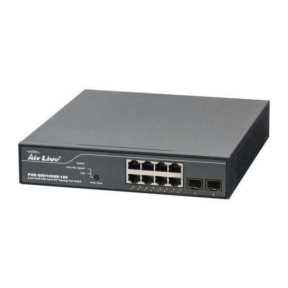
Introduction 1.1 Overview The POE-GSH1008R-130 is a 8-port Gigabit TP L2 PoE switch with 2-Port Gigabit TP/SFP slots. This Switch can power on 802.3at/af cameras by RJ45 cable. Web-based management unit, associated with SNMP agent allow user access the switch remotely. In... -
Page 6: How To Use This Guide
1. Introduction 1.2 How to Use This Guide POE-GSH1008R-130 is a SNMP and web smart PoE Switch with many functions. It is recommended that you read through the entire user’s guide whenever possible. The user guide is divided into different chapters. You should read at least go through the first 2 chapters before attempting to install the device. -
Page 7: Installing The Poe-Gsh1008R-130
POE-GSH1008R-130. For software configuration, please go to chapter 3 for more details. 2.1 Before You Start It is important to read through this section before you install the POE-GSH1008R-130 The maximum cabling distance is 100 meters by Cat5e RJ45 cable. -
Page 8: Optional Accessory
2. Installing the POE-GSH1008R-130 Compare the contents of your POE-GSH1008R-130 package with the standard checklist above. If any item is missing or damaged, please contact your local dealer for service. 2.3 Optional Accessory The POE-GSH1008R-130 has the following optional accessories which you can purchase from AirLive ... -
Page 9: Knowing Your Poe-Gsh1008R-130
Below are descriptions and diagrams of the product: 2.5 Hardware Installation Set the POE-GSH1008R-130 on a sufficiently large flat space with a power outlet nearby. The surface where you put your POE-GSH1008R-130 should be clean, smooth, level and sturdy. Make sure there is enough clearance around the POE-GSH1008R-130 to allow attachment of cables, power cord and allow air circulation. - Page 10 2. Installing the POE-GSH1008R-130 2.5.2. Rack-mounted Installation The POE-GSH1008R-130 comes with a rack-mounted kid and can be mounted in an EIA standard size, 19-inch Rack (Rack-mounted is option). The POE-GSH1008R-130 can be placed in a wiring closet with other equipment. Perform the following steps to rack mount...
-
Page 11: Led Table
2.5.3. Power On Connect the power cord to the power socket on the rear panel of the POE-GSH1008R-130. The other side of power cord connects to the power outlet. The internal power supply of the POE-GSH1008R-130 works with voltage range of AC in the 100-240VAC, frequency 50~60Hz. - Page 12 2. Installing the POE-GSH1008R-130 Status Description System Green Power is ON Green On Link up 1000M Link/ACT/Speed Yellow On Link up 100M Blinking Data activating Green PoE device connecting AirLive POE-GSH1008R-130 User Manual...
-
Page 13: Introduce The Poe-Gsh1008R-130
The default password is airlive 3.2 Prepare your PC The POE-GSH1008R-130 can be managed remotely by a PC through RJ-45 cable. The default IP address of the POE-GSH1008R-130 is 192.168.2.1 with a subnet mask of 255.255.255.0. This means the IP address of the PC should be in the range of 192.168.2.2 to 192.168.2.253. -
Page 14: Introduction To Web Management
Web Management (HTTP): You can manage your POE-GSH1008R-130 by simply typing its IP address in the web browser. Most functions of POE-GSH1008R-130 can be accessed by web management inter face. We recommend using this interface for initial configurations. To begin, simply enter POE-GSH1008R-130’s IP address (default is 192.168.2.1) on the web browser. - Page 15 Click “Enter” or ”Login”, then the home screen of the Web-based management appears. 3.4.2. Menu Structure of POE-GSH1008R-130 The web management menu of POE-GSH1008R-130 is divided into 3 parts: Top Bar, Side Menu Bar, and Main Screen. Top Bar Main Screen...
- Page 16 3. Introduce the POE-GSH1008R-130 Top Bar: It display panel GUI. You can direct click the port on the Switch figure on the top of web page. Then, you will see the port information. On the left-top corner, there is a pull-down list for Auto Logout. For the sake of security, we provide auto-logout function to protect you from illegal user as you are leaving.
-
Page 17: Web Management: System Of Poe-Gsh1008R-130
4.Web Management: System of POE-GSH1008R-130 Web Management: System of POE-GSH1008R-130 4.1 System This chapter describes the entire basic configuration tasks which includes the System Information and any manage of the Switch (e.g. Time, Account, IP, Syslog and NTP.) 4.1.1. System Information You can identify the system by configuring the contact information, name, and location of the switch. - Page 18 4.Web Management: System of POE-GSH1008R-130 Parameter description: Model Name Model Name will show POE-GSH1008R-130 by different models System Description Displays the system description. Hardware-Mechanical Version The hardware and mechanical version of this switch. Firmware Version The software version of this switch.
- Page 19 The period of time the device has been operational. 4.1.2. Advance IP Setting This sector is to provide and config the IP information of the POE-GSH1008R-130. 4.1.2.1. IP Configuration The IPv4 address for the switch could be obtained via DHCP Server for VLAN 1. To manually configure an address, you need to change the switch's default settings to values that are compatible with your network.
- Page 20 4.Web Management: System of POE-GSH1008R-130 Parameter description: IP Configuration DNS Server This setting controls the DNS name resolution done by the switch. The following modes are supported: • From any DHCP interfaces The first DNS server offered from a DHCP lease to a DHCP-enabled interface will be used.
- Page 21 4.Web Management: System of POE-GSH1008R-130 VLAN The VLAN associated with the IP interface. Only ports in this VLAN will be able to access the IP interface. This field is only available for input when creating an new interface. IPv4 DHCP Enabled Enable the DHCP client by checking this box.
- Page 22 4.Web Management: System of POE-GSH1008R-130 IPv6 Mask The IPv6 network mask, in number of bits (prefix length). Valid values are between 1 and 128 bits for a IPv6 address. The field may be left blank if IPv6 operation on the interface is not desired.
- Page 23 4.Web Management: System of POE-GSH1008R-130 Apply: Click to save changes. Reset: Click to undo any changes made locally and revert to previously saved values. 4.1.2.2. IP Status This page displays the status of the IP protocol layer. The status is defined by the IP interfaces, the IP routes and the neighbor cache (ARP cache) status.
- Page 24 4.Web Management: System of POE-GSH1008R-130 AirLive POE-GSH1008R-130 User Manual...
- Page 25 4.Web Management: System of POE-GSH1008R-130 Parameter description: IP Interfaces Interface Show the name of the interface. Type Show the address type of the entry. This may be LINK or IPv4. Address Show the current address of the interface (of the given type).
- Page 26 4.Web Management: System of POE-GSH1008R-130 Link Address Show the Link (MAC) address for which a binding to the IP address given exist. Buttons Auto-refresh: Check this box to refresh the page automatically. Automatic refresh occurs every 3 seconds. Refresh: Click to refresh the page immediately.
- Page 27 4.Web Management: System of POE-GSH1008R-130 Parameter description: Time Configuration Clock Source: There are two modes for configuring how the Clock Source from. Select "Use Local Settings" : Clock Source from Local Time. Select "Use NTP Server" : Clock Source from NTP Server.
- Page 28 4.Web Management: System of POE-GSH1008R-130 Acronym: User can set the acronym of the time zone. This is a User configurable acronym to identify the time zone. ( Range : Up to 16 characters ) Daylight Saving Time Configuration Daylight Saving Time: This is used to set the clock forward or backward according to the configurations set below for a defined Daylight Saving Time duration.
- Page 29 4.Web Management: System of POE-GSH1008R-130 Time Settings” was displayed what you set on the “Start Time Settings” and “End Time Settings” field information. Buttons These buttons are displayed on the NTP page: Apply – Click to save changes. Reset - Click to undo any changes made locally and revert to previously saved values.
- Page 30 4.Web Management: System of POE-GSH1008R-130 Parameter description: Mode : Indicates the NTP mode operation. Possible modes are: Enabled: Enable NTP client mode operation. Disabled: Disable NTP client mode operation. Server 1 to 5 : Provide the NTP IPv4 or IPv6 address of this switch. IPv6 address is in 128-bit records represented as eight fields of up to four hexadecimal digits with a colon separating each field (:).
- Page 31 4.Web Management: System of POE-GSH1008R-130 4.1.4. Log The log is a standard for logging program messages . It allows separation of the software that generates messages from the system that stores them and the software that reports and analyzes them. It can be used as well a generalized informational, analysis and debugging messages.
- Page 32 4.Web Management: System of POE-GSH1008R-130 Enabled: Enable server mode operation. Disabled: Disable server mode operation. Server Address : Indicates the IPv4 hosts address of syslog server. If the switch provide DNS feature, it also can be a host name. Syslog Level : Indicates what kind of message will send to syslog server.
- Page 33 4.Web Management: System of POE-GSH1008R-130 2. Modify LLDP timing parameters 3. Set the required mode for transmitting or receiving LLDP messages 4. Specify the information to include in the TLV field of advertised messages 5. Click Apply AirLive POE-GSH1008R-130 User Manual...
- Page 34 4.Web Management: System of POE-GSH1008R-130 Parameter description: LLDP Parameters Tx Interval : The switch periodically transmits LLDP frames to its neighbours for having the network discovery information up-to-date. The interval between each LLDP frame is determined by the Tx Interval value. Valid values are restricted to 5 - 32768 seconds.
- Page 35 4.Web Management: System of POE-GSH1008R-130 Tx Delay : If some configuration is changed (e.g. the IP address) a new LLDP frame is transmitted, but the time between the LLDP frames will always be at least the value of Tx Delay seconds. Tx Delay cannot be larger than 1/4 of the Tx Interval value.
- Page 36 4.Web Management: System of POE-GSH1008R-130 CDP TLV "Device ID" is mapped to the LLDP "Chassis ID" field. CDP TLV "Address" is mapped to the LLDP "Management Address" field. The CDP address TLV can contain multiple addresses, but only the first address is shown in the LLDP neighbors’...
- Page 37 4.Web Management: System of POE-GSH1008R-130 Buttons: Apply – Click to save changes. Reset- Click to undo any changes made locally and revert to previously saved values. 4.1.5.2. LLDP-MED Configuration Media Endpoint Discovery is an enhancement of LLDP, known as LLDP-MED that provides...
- Page 38 4.Web Management: System of POE-GSH1008R-130 AirLive POE-GSH1008R-130 User Manual...
- Page 39 4.Web Management: System of POE-GSH1008R-130 Parameter description: Fast start repeat count Rapid startup and Emergency Call Service Location Identification Discovery of endpoints is a critically important aspect of VoIP systems in general. In addition, it is best to advertise only those pieces of information which are specifically relevant to particular endpoint types...
- Page 40 4.Web Management: System of POE-GSH1008R-130 Longitude : Longitude SHOULD be normalized to within 0-180 degrees with a maximum of 4 digits. It is possible to specify the direction to either East of the prime meridian or West of the prime meridian.
- Page 41 4.Web Management: System of POE-GSH1008R-130 State : National subdivisions (state, canton, region, province, prefecture). County : County, parish, gun (Japan), district. City : City, township, shi (Japan) - Example: Copenhagen. City district : City division, borough, city district, ward, chou (Japan).
- Page 42 4.Web Management: System of POE-GSH1008R-130 17. Building : Building (structure) - Example: Low Library. 18. Apartment : Unit (Apartment, suite) - Example: Apt 42. 19. Floor : Floor - Example: 4. 20. Room no. : Room number - Example: 450F.
- Page 43 4.Web Management: System of POE-GSH1008R-130 Policies are only intended for use with applications that have specific 'real-time' network policy requirements, such as interactive voice and/or video services. The network policy attributes advertised are: 1. Layer 2 VLAN ID (IEEE 802.1Q-2003) 2.
- Page 44 4.Web Management: System of POE-GSH1008R-130 1. Voice - for use by dedicated IP Telephony handsets and other similar appliances supporting interactive voice services. These devices are typically deployed on a separate VLAN for ease of deployment and enhanced security by isolation from data applications.
- Page 45 4.Web Management: System of POE-GSH1008R-130 Untagged indicates that the device is using an untagged frame format and as such does not include a tag header as defined by IEEE 802.1Q-2003. In this case, both the VLAN ID and the Layer 2 priority fields are ignored and only the DSCP value has relevance.
- Page 46 4.Web Management: System of POE-GSH1008R-130 12. Buttons: Apply – Click to save changes. Reset- Click to undo any changes made locally and revert to previously saved values. 4.1.5.3. LLDP Neighbor This page provides a status overview for all LLDP neighbors. The displayed table contains a row for each port on which an LLDP neighbor is detected.
- Page 47 4.Web Management: System of POE-GSH1008R-130 System Name : System Name is the name advertised by the neighbour unit. System Capabilities : System Capabilities describes the neighbour unit's capabilities. The possible capabilities are: 1. Other 2. Repeater 3. Bridge 4. WLAN Access Point 5.
- Page 48 4.Web Management: System of POE-GSH1008R-130 Web Interface To show LLDP-MED neighbor: Click Monitor, LLDP, LLDP-MED Neighbor. Click Refresh for manual update web screen Click Auto-refresh for auto-update web screen Parameter description: Port : The port on which the LLDP frame was received.
- Page 49 4.Web Management: System of POE-GSH1008R-130 Within the LLDP-MED Endpoint Device category, the LLDP-MED scheme is broken into further Endpoint Device Classes, as defined in the following. Each LLDP-MED Endpoint Device Class is defined to build upon the capabilities defined for the previous Endpoint Device Class. For-example will any LLDP-MED...
- Page 50 4.Web Management: System of POE-GSH1008R-130 Discovery services defined in this class include provision of location identifier (including ECS / E911 information), embedded L2 switch support, inventory management. LLDP-MED Capabilities : LLDP-MED Capabilities describes the neighborhood unit's LLDP-MED capabilities. The possible capabilities are: 1.
- Page 51 4.Web Management: System of POE-GSH1008R-130 7. Streaming Video - for use by broadcast or multicast based video content distribution and other similar applications supporting streaming video services that require specific network policy treatment. Video applications relying on TCP with buffering would not be an intended use of this application type.
- Page 52 4.Web Management: System of POE-GSH1008R-130 11. Auto-negotiation status Auto-negotiation status identifies if auto-negotiation is currently enabled at the link partner. If Auto-negotiation is supported and Auto-negotiation status is disabled, the 802.3 PMD operating mode will be determined the operational MAU type field value rather than by auto-negotiation.
- Page 53 4.Web Management: System of POE-GSH1008R-130 Parameter description: Global Counters Neighbor entries were last changed at : It also shows the time when the last entry was last deleted or added. It also shows the time elapsed since the last change was detected.
- Page 54 4.Web Management: System of POE-GSH1008R-130 Total Neighbors Entries Added : Shows the number of new entries added since switch reboot. Total Neighbors Entries Deleted : Shows the number of new entries deleted since switch reboot. Total Neighbors Entries Dropped : Shows the number of LLDP frames dropped due to the entry table being full.
- Page 55 4.Web Management: System of POE-GSH1008R-130 TLVs Unrecognized : The number of well-formed TLVs, but with an unknown type value. Org. Discarded : The number of organizationally received TLVs. Age-Outs : Each LLDP frame contains information about how long time the LLDP information is valid (age-out time).
- Page 56 4.Web Management: System of POE-GSH1008R-130 Parameter description: These parameters are displayed on the UPnP Configuration page: Mode : Indicates the UPnP operation mode. Possible modes are: Enabled: Enable UPnP mode operation. Disabled: Disable UPnP mode operation. When the mode is enabled, two ACEs are added automatically to trap UPNP related packets to CPU.
-
Page 57: Port Management
4.Web Management: System of POE-GSH1008R-130 4.2 Port Management 4.2.1. Port Configuration The section describes to configure the Port detail parameters of the switch. Others you could using the Port configure to enable or disable the Port of the switch. Monitor the ports content or status in the function. - Page 58 4.Web Management: System of POE-GSH1008R-130 Parameter description: Port : This is the logical port number for this row. Link : The current link state is displayed graphically. Green indicates the link is up and red that it is down. Current Link Speed : Provides the current link speed of the port.
- Page 59 4.Web Management: System of POE-GSH1008R-130 10Mbps HDX - Forces the cu port in 10Mbps half duplex mode. 10Mbps FDX - Forces the cu port in 10Mbps full duplex mode. 100Mbps HDX - Forces the cu port in 100Mbps half duplex mode.
- Page 60 4.Web Management: System of POE-GSH1008R-130 Buttons Apply – Click to save changes. Reset- Click to undo any changes made locally and revert to previously saved values. Upper right icon (Refresh) You can click them for refresh the Port link Status by manual 4.2.2.
- Page 61 4.Web Management: System of POE-GSH1008R-130 Parameter description: Port : The logical port for the settings contained in the same row. Packets : The number of received and transmitted packets per port. Bytes : The number of received and transmitted bytes per port.
- Page 62 4.Web Management: System of POE-GSH1008R-130 Drops The number of frames discarded due to ingress or egress congestion. Filtered The number of received frames filtered by the forwarding Buttons Auto-refresh: Check this box to refresh the page automatically. Automatic refresh occurs every 3 seconds.
- Page 63 4.Web Management: System of POE-GSH1008R-130 Parameter description: Auto-refresh: To evoke the auto-refresh to refresh the Port Statistics information automatically. AirLive POE-GSH1008R-130 User Manual...
- Page 64 4.Web Management: System of POE-GSH1008R-130 Upper left scroll bar: To scroll which port to display the Port statistics with “Port-0”, “Port-1... Receive Total and Transmit Total Rx and Tx Packets : The number of received and transmitted (good and bad) packets.
- Page 65 4.Web Management: System of POE-GSH1008R-130 Rx Oversize : The number of long 2 frames received with valid CRC. Rx Fragments : The number of short 1 frames received with invalid CRC. Rx Jabber : The number of long 2 frames received with invalid CRC.
- Page 66 4.Web Management: System of POE-GSH1008R-130 4.2.3. SFP Port Info The section describes that switch could display the SFP module detail information which you connect it to the switch. The information includes: Connector type, Fiber type, wavelength, baud rate and Vendor OUI etc.
- Page 67 4.Web Management: System of POE-GSH1008R-130 Display the fiber optical transmitting central wavelength, for instance, 850nm, 1310nm, 1550nm and so on. Baud Rate: Display the maximum baud rate of the fiber module supported, for instance, 10M, 100M, 1G and so on.
- Page 68 4.Web Management: System of POE-GSH1008R-130 circuits powered up when traffic is transmitted. The devices can exchange wakeup time information using the LLDP protocol. EEE works for ports in auto-negotiation mode, where the port is negotiated to either 1G or 100 Mbit full duplex mode.
- Page 69 4.Web Management: System of POE-GSH1008R-130 Parameter description: Optimize EEE for The switch can be set to optimize EEE for either best power saving or least traffic latency. EEE : Controls whether EEE is enabled for this switch port. AirLive POE-GSH1008R-130 User Manual...
- Page 70 4.Web Management: System of POE-GSH1008R-130 For maximizing power savings, the circuit isn't started at once transmit data is ready for a port, but is instead queued until a burst of data is ready to be transmitted. This will give some traffic latency.
- Page 71 4.Web Management: System of POE-GSH1008R-130 Parameter description: Port : The switch port number. Method Controls whether LACP is enabled on this switch port. LACP will form an aggregation when 2 or more ports are connected to the same partner. AirLive POE-GSH1008R-130 User Manual...
- Page 72 4.Web Management: System of POE-GSH1008R-130 The Key value incurred by the port, range 1-65535 . The Auto setting will set the key as appropriate by the physical link speed, 10Mb = 1, 100Mb = 2, 1Gb = 3. Using the Specific setting, a user-defined value can be entered. Ports with the same Key value can participate in the same aggregation group, while ports with different keys cannot.
- Page 73 4.Web Management: System of POE-GSH1008R-130 Parameter description: Aggregator : The Aggregation ID associated with this aggregation instance. For LLAG the id is shown as 'isid: aggr-id' and for GLAGs as 'aggr-id' Method Member Ports Ready Ports Lacp Detail AirLive POE-GSH1008R-130 User Manual...
- Page 74 4.Web Management: System of POE-GSH1008R-130 4.2.5.3. Aggregation Mode Configuration This section describes that when you complete to set LACP function on the switch then it provides a Port Status overview for all LACP instances Web Interface To display the LACP Port status in the web interface: 1.
- Page 75 4.Web Management: System of POE-GSH1008R-130 Parameter description: System Priority Buttons Apply : Click to save changes. Reset : Click to undo any changes made locally and revert to previously saved values. 4.2.6. Loop Protection The loop Protection is used to detect the presence of traffic. When switch receives packet’s (looping detection frame) MAC address the same as oneself from port, show Loop Protection happens.
- Page 76 4.Web Management: System of POE-GSH1008R-130 AirLive POE-GSH1008R-130 User Manual...
-
Page 77: Poe Management
Reset : Click to undo any changes made locally and revert to previously saved values. 4.3 PoE Management POE-GSH1008R-130 support 802.3at/af Power-Over-Ethernet (PoE). Each port can provide up to 30W power with Data on RJ45 cable. The PoE detect function is follow the table... - Page 78 4.Web Management: System of POE-GSH1008R-130 Power levels available Power range Class Usage Class description [Watt] Default 15.4 Classification unimplemented Optional Very Low power Optional Low power Optional 15.4 Mid power Valid for 802.3at (Type 2) devices, not allowed High power for 802.3af devices...
- Page 79 4.Web Management: System of POE-GSH1008R-130 Parameter description: Power Supply Configuration Primary Power Supply : Valid values are in the range 0 to 250 Watts. Port : This is the logical port number for this row. Ports that are not PoE-capable are grayed out and thus impossible to configure PoE for.
- Page 80 4.Web Management: System of POE-GSH1008R-130 Parameter description: Local Port This is the logical port number for this row. PD Class Each PD is classified according to a class that defines the maximum power the PD will use. The PD Class shows the PDs class.
- Page 81 4.Web Management: System of POE-GSH1008R-130 Port Status The Port Status shows the port's status. The status can be one of the following values: PoE not available - No PoE chip found - PoE not supported for the port. PoE turned OFF - PoE disabled : PoE is disabled by user.
- Page 82 4.Web Management: System of POE-GSH1008R-130 Parameter description: Power Supply Configuration Port : This is the logical port number for this row. Delay Mode : Turn on / off the power delay function. Enabled: Enable POE Power Delay. Disabled: Disable POE Power Delay.
- Page 83 4.Web Management: System of POE-GSH1008R-130 Click Apply to apply the change. Parameter description: Power Supply Configuration Ping Check : Enable Ping Check function can detects the connection between PoE port and power device. Disable will turn off the detection. Port : This is the logical port number for this row.
- Page 84 4.Web Management: System of POE-GSH1008R-130 Nothing: Keep Ping the remote PD but does nothing further. Reboot Remote PD: Cut off the power of the PoE port, make PD rebooted. Reboot time(sec) : When PD has been rebooted, the PoE port restored power after the specified time.
-
Page 85: Vlan Management
4.Web Management: System of POE-GSH1008R-130 Buttons Apply : Click to save changes. Reset : Click to undo any changes made locally and revert to previously saved values. 4.4 VLAN Management To assign a specific VLAN for management purpose. The management VLAN is used to establish an IP connection to the switch from a workstation connected to a port in the VLAN. - Page 86 4.Web Management: System of POE-GSH1008R-130 Parameter description: Global VLAN Configuration AirLive POE-GSH1008R-130 User Manual...
- Page 87 4.Web Management: System of POE-GSH1008R-130 Allowed Access VLANs : This field shows the VLANs that are created on the switch. By default, only VLAN 1 exists. More VLANs may be created by using a list syntax where the individual elements are separated by commas. Ranges are specified with a dash separating the lower and upper bound.
- Page 88 4.Web Management: System of POE-GSH1008R-130 • By default, a trunk port is member of all existing VLANs. This may be limited by the use of Allowed VLANs, • unless VLAN Trunking is enabled on the port, frames classified to a VLAN that the port is not a member of will be discarded, •...
- Page 89 4.Web Management: System of POE-GSH1008R-130 C-Port: On ingress, frames with a VLAN tag with TPID = 0x8100 get classified to the VLAN ID embedded in the tag. If a frame is untagged or priority tagged, the frame gets classified to the Port VLAN. If frames must be tagged on egress, they will be tagged with a C-tag.
- Page 90 4.Web Management: System of POE-GSH1008R-130 Tagged and Untagged Both tagged and untagged frames are accepted. Tagged Only Only tagged frames are accepted on ingress. Untagged frames are discarded. Untagged Only Only untagged frames are accepted on ingress. Tagged frames are discarded.
- Page 91 4.Web Management: System of POE-GSH1008R-130 4.4.2. VLAN Membership This page provides an overview of membership status of VLAN users. The ports belong to the currently selected stack unit, as reflected by the page header. Web Interface To configure VLAN membership configuration in the web interface: Click Monitor, VLANs, VLAN membership.
- Page 92 4.Web Management: System of POE-GSH1008R-130 MVR : MVR is used to eliminate the need to duplicate multicast traffic for subscribers in each VLAN. Multicast traffic for all channels is sent only on a single (multicast) VLAN. MSTP : The 802.1s Multiple Spanning Tree protocol (MSTP) uses VLANs to create multiple spanning trees in a network, which significantly improves network resource utilization while maintaining a loop-free environment.
- Page 93 4.Web Management: System of POE-GSH1008R-130 Auto-refresh: Check this box to refresh the page automatically. Automatic refresh occurs every 3 seconds. Refresh: Click to refresh the page. 4.4.3. VLAN Port Status The function Port Status gathers the information of all VLAN status and reports it by the order of Static NAS MVRP MVP Voice VLAN MSTP GVRP Combined.
- Page 94 4.Web Management: System of POE-GSH1008R-130 CLI/Web/SNMP : These are referred to as static. NAS : NAS provides port-based authentication, which involves communications between a Supplicant, Authenticator, and an Authentication Server. Voice VLAN : Voice VLAN is a VLAN configured specially for voice traffic typically originating from IP phones.
- Page 95 4.Web Management: System of POE-GSH1008R-130 Tx Tag : Shows egress filtering frame status whether tagged or untagged. Buttons Auto-refresh: Check this box to refresh the page automatically. Automatic refresh occurs every 3 seconds. Refresh: Click to refresh the page. 4.4.4. VLAN Selective QinQ...
- Page 96 4.Web Management: System of POE-GSH1008R-130 4.4.5. MAC-Base VLAN5 MAC address-based VLAN decides the VLAN for forwarding an untagged frame based on the source MAC address of the frame. A most common way of grouping VLAN members is by port, hence the name port-based VLAN.
- Page 97 4.Web Management: System of POE-GSH1008R-130 MAC Address : Indicates the MAC address. VLAN ID : Indicates the VLAN ID. Port Members : A row of check boxes for each port is displayed for each MAC-based VLAN entry. To include a port in a MAC-based VLAN, check the box. To remove or exclude the port from the MAC-based VLAN, make sure the box is unchecked.
- Page 98 4.Web Management: System of POE-GSH1008R-130 SNAP The Subnetwork Access Protocol (SNAP) is a mechanism for multiplexing, on networks using IEEE 802.2 LLC, more protocols than can be distinguished by the 8-bit 802.2 Service Access Point (SAP) fields. SNAP supports identifying protocols by Ethernet type field values;...
- Page 99 4.Web Management: System of POE-GSH1008R-130 2. For LLC: Valid value in this case is comprised of two different sub-values. a. DSAP: 1-byte long string (0x00-0xff) b. SSAP: 1-byte long string (0x00-0xff) 3. For SNAP: Valid value in this case also is comprised of two different sub-values.
- Page 100 4.Web Management: System of POE-GSH1008R-130 Web Interface To Display Group Name to VLAN mapping table configured in the web interface: Click Group Name VLAN configuration and add new entry. Specify the Group Name and VLAN ID. Click Apply. Figure 4.4.7: The Group Name of VLAN Mapping Table...
- Page 101 4.Web Management: System of POE-GSH1008R-130 Reset- Click to undo any changes made locally and revert to previously saved values. Auto-refresh : To evoke the auto-refresh icon then the device will refresh the information automatically. Upper right icon (Refresh): You can click them for refresh the Protocol Group Mapping information by manual.
- Page 102 4.Web Management: System of POE-GSH1008R-130 4.4.7.1. Private VLAN The VLAN membership configuration for the selected stack switch unit switch can be monitored and modified here. Up to 4096 VLANs are supported. This page allows for adding and deleting VLANs as well as adding and deleting port members of each VLAN.
- Page 103 4.Web Management: System of POE-GSH1008R-130 A VLAN without any port members on any stack unit will be deleted when you click "Save". The button can be used to undo the addition of new VLANs. Buttons: Apply – Click to save changes.
- Page 104 4.Web Management: System of POE-GSH1008R-130 Parameter description: Port Members : A check box is provided for each port of a private VLAN. When checked, port isolation is enabled on that port. When unchecked, port isolation is disabled on that port. By default, port isolation is disabled on all ports.
- Page 105 4.Web Management: System of POE-GSH1008R-130 Parameter description: Mode : Indicates the Voice VLAN mode operation. We must disable MSTP feature before we enable Voice VLAN. It can avoid the conflict of ingress filtering. Possible modes are: AirLive POE-GSH1008R-130 User Manual...
- Page 106 4.Web Management: System of POE-GSH1008R-130 Enabled: Enable Voice VLAN mode operation. Disabled: Disable Voice VLAN mode operation. VLAN ID : Indicates the Voice VLAN ID. It should be a unique VLAN ID in the system and cannot equal each port PVID. It is a conflict in configuration if the value equals management VID, MVR VID, PVID etc.
- Page 107 4.Web Management: System of POE-GSH1008R-130 Buttons: Apply – Click to save changes. Reset- Click to undo any changes made locally and revert to previously saved values. 4.4.9.2. OUI The section describes to Configure VOICE VLAN OUI table . The maximum entry number is 16.
-
Page 108: Quality Of Service
4.Web Management: System of POE-GSH1008R-130 Buttons: Apply – Click to save changes. Reset- Click to undo any changes made locally and revert to previously saved values. 4.5 Quality of Service The switch support four QoS queues per port with strict or weighted fair queuing scheduling. - Page 109 4.Web Management: System of POE-GSH1008R-130 DSCP The section will teach user to set the QoS Port DSCP configuration that was allowed you to configure the basic QoS Port DSCP Configuration settings for all switch ports. Others the settings relate to the currently selected stack unit, as reflected by the page header.
- Page 110 4.Web Management: System of POE-GSH1008R-130 CoS : Controls the default class of service. All frames are classified to a CoS. There is a one to one mapping between CoS, queue and priority. A CoS of 0 (zero) has the lowest priority.
- Page 111 4.Web Management: System of POE-GSH1008R-130 Parameter description: Port : The logical port for the settings contained in the same row. Click on the port number in order to configure the schedulers. Enabled : To evoke which Port you need to enable the QoS Ingress Port Policers function.
- Page 112 4.Web Management: System of POE-GSH1008R-130 Buttons: Apply – Click to save changes. Reset- Click to undo any changes made locally and revert to previously saved values. 4.5.4. Port Shapers This section provides an overview of QoS Egress Port Shapers for all switch ports. Others the user could get all detail information ot the ports belong to the currently selected stack unit, as reflected by the page header.
- Page 113 4.Web Management: System of POE-GSH1008R-130 Parameter description: Port : The logical port for the settings contained in the same row. Click on the port number in order to configure the shapers. Mode : Shows the scheduling mode for this port.
- Page 114 4.Web Management: System of POE-GSH1008R-130 4.5.5. Storm Control The section allows user to configure the Storm control for the switch. There is a unicast storm rate control, multicast storm rate control, and a broadcast storm rate control. These only affect flooded frames, i.e. frames with a (VLAN ID, DMAC) pair not present on the MAC Address table.
- Page 115 4.Web Management: System of POE-GSH1008R-130 Parameter description: Enable : Enable or disable the storm control status for the given frame type. Rate : The rate unit is packets per second (pps). Valid values are: 1, 2, 4, 8, 16, 32, 64, 128, 256, 512, 1K, 2K, 4K, 8K, 16K, 32K, 64K, 128K, 256K, 512K or 1024K.
- Page 116 4.Web Management: System of POE-GSH1008R-130 Web Interface To display the QoS Port Schedulers in the web interface: 1. Click Configuration, QoS, Port Schedulers 2. Display the QoS Egress Port Schedulers AirLive POE-GSH1008R-130 User Manual...
- Page 117 4.Web Management: System of POE-GSH1008R-130 Parameter description: Port : The logical port for the settings contained in the same row. Click on the port number in order to configure the schedulers. Mode : Shows the scheduling mode for this port.
-
Page 118: Web Interface
4.Web Management: System of POE-GSH1008R-130 Parameter description: CoS/802.1p (QoS class, DP level) to (PCP, DEI) Mapping : Controls the mapping of the classified (QoS class, DP level) to (PCP, DEI) values when the mode is set to Mapped. Buttons: Apply – Click to save changes. - Page 119 4.Web Management: System of POE-GSH1008R-130 Apply – Click to save changes. Reset- Click to undo any changes made locally and revert to previously saved values. 4.5.9. QoS Ingress IP Precedence to Queue Mapping In Ingress settings you can change ingress translation and classification settings for individual ports.
-
Page 120: Dscp Mapping
4.Web Management: System of POE-GSH1008R-130 4.5.10. QoS Egress Queue to IP Precedence Remarking Web Interface To display the QoS Egress Queue to IP Precedence Remarking in the web interface: Click Configuration, QoS, QoS Egress Queue to IP Precedence Remarking Parameter description:... - Page 121 4.Web Management: System of POE-GSH1008R-130 If you want to cancel the setting then you need to click the Reset button. It will revert to previously saved values Parameter description: DSCP : Maximum number of supported DSCP values are 64 and valid DSCP value ranges from 0 to 63.
- Page 122 4.Web Management: System of POE-GSH1008R-130 Reset- Click to undo any changes made locally and revert to previously saved values. 4.5.12. DSCP Remarking The section will teach user to set the QoS ingress DSCP to queue remarking. Web Interface To configure the QoS Port DSCP parameters in the web interface:...
-
Page 123: Spanning Tree
4.Web Management: System of POE-GSH1008R-130 Buttons: Apply – Click to save changes. Reset- Click to undo any changes made locally and revert to previously saved values. 4.6 Spanning Tree The Spanning Tree Protocol (STP) can be used to detect and disable network loops, and to provide backup links between switches, bridges or routers. - Page 124 4.Web Management: System of POE-GSH1008R-130 2. Scroll to select the parameters and write down available value of parameters in blank field in Basic Settings 3. Evoke to enable or disable the parameters and write down available value of parameters in blank field in Advanced settings 4.
- Page 125 4.Web Management: System of POE-GSH1008R-130 Parameter description: Region Name : The name identifying the VLAN to MSTI mapping. Bridges must share the name and revision (see below), as well as the VLAN-to-MSTI mapping configuration in order to share spanning trees for MSTI's (Intra-region). The name is at most 32 characters.
-
Page 126: Mac Address Tables
4.Web Management: System of POE-GSH1008R-130 Parameter description: Instance ID : a device identification string that distinguishes a device from other devices of the same type on a computer. Corresponding Vlans Buttons Add Vlan: Add Vlan Mapping Delete : Delete setting... - Page 127 4.Web Management: System of POE-GSH1008R-130 MAC Table Learning Click configuration . Specify the Port Members(Auto,Disable,Secure). Click Apply. Static MAC Table Configuration Click configuration and Add new Static entry . Specify the VLAN IP and Mac address ,Port Members. Click Apply.
- Page 128 4.Web Management: System of POE-GSH1008R-130 Disable the automatic aging of dynamic entries by checking Disable automatic aging. MAC Table Learning If the learning mode for a given port is greyed out, another module is in control of the mode, so that it cannot be changed by the user. An example of such a module is the MAC-Based Authentication under 802.1X.
- Page 129 4.Web Management: System of POE-GSH1008R-130 Port Members : Checkmarks indicate which ports are members of the entry. Check or uncheck as needed to modify the entry. Adding a New Static Entry : Click to add a new entry to the static MAC table. Specify the VLAN ID, MAC address, and port members for the new entry.
- Page 130 4.Web Management: System of POE-GSH1008R-130 Parameter description: Navigating the MAC Table Each page shows up to 999 entries from the MAC table, default being 20, selected through the "entries per page" input field. When first visited, the web page will show the first 20 entries from the beginning of the MAC Table.
-
Page 131: Multicast
4.Web Management: System of POE-GSH1008R-130 MAC Table Columns Type : Indicates whether the entry is a static or a dynamic entry. VLAN : The VLAN ID of the entry. MAC address : The MAC address of the entry. Port Members : The ports that are members of the entry. - Page 132 4.Web Management: System of POE-GSH1008R-130 A switch supported IGMP Snooping with the functions of query, report and leave, a type of packet exchanged between IP Multicast Router/Switch and IP Multicast Host, can update the information of the Multicast table when a member (port) joins or leaves an IP Multicast Destination Address.
- Page 133 4.Web Management: System of POE-GSH1008R-130 Parameter description: Snooping Enabled: Enable the Global IGMP Snooping. Unregistered IPMCv4 Flooding enabled : Enable unregistered IPMCv4 traffic flooding. IGMP SSM Range : SSM (Source-Specific Multicast) Range allows the SSM-aware hosts and routers run the SSM service model for the groups in the address range. Format: (IP...
- Page 134 4.Web Management: System of POE-GSH1008R-130 Proxy Enabled : Enable IGMP Proxy. This feature can be used to avoid forwarding unnecessary join and leave messages to the router side. Port : It shows the physical Port index of switch. Router Port : Specify which ports act as router ports.
- Page 135 4.Web Management: System of POE-GSH1008R-130 Parameter description: Delete : Check to delete the entry. The designated entry will be deleted during the next save. VLAN ID : It displays the VLAN ID of the entry. IGMP Snooping Enabled : Enable the per-VLAN IGMP Snooping. Only up to 32 VLANs can be selected. .
- Page 136 4.Web Management: System of POE-GSH1008R-130 Rv : Robustness Variable. The Robustness Variable allows tuning for the expected packet loss on a network. The allowed range is 1 to 255; default robustness variable value is 2. QI : Query Interval. The Query Interval is the interval between General Queries sent by the Querier.
- Page 137 4.Web Management: System of POE-GSH1008R-130 If you want to auto-refresh the information then you need to evoke the “Auto-refresh”. Click “ Refresh“ to refresh the IGMP Snooping Status. Click “ Clear“ to clear the IGMP Snooping Status. AirLive POE-GSH1008R-130 User Manual...
- Page 138 4.Web Management: System of POE-GSH1008R-130 Parameter description: VLAN ID : The VLAN ID of the entry. Querier Version : Working Querier Version currently. Host Version : Working Host Version currently. Querier Status : Shows the Querier status is "ACTIVE" or "IDLE".
- Page 139 4.Web Management: System of POE-GSH1008R-130 13. Status Indicate whether specific port is a router port or not. 14. Buttons Auto-refresh: Check this box to refresh the page automatically. Automatic refresh occurs every 3 seconds. Refresh: Click to refresh the page.
- Page 140 4.Web Management: System of POE-GSH1008R-130 Parameter description: Navigating the IGMP Group Table Each page shows up to 99 entries from the IGMP Group table, default being 20, selected through the "entries per page" input field. When first visited, the web page will show the first 20 entries from the beginning of the IGMP Group Table.
- Page 141 4.Web Management: System of POE-GSH1008R-130 Auto-refresh: Check this box to refresh the page automatically. Automatic refresh occurs every 3 seconds. Refresh: Click to refresh the page. |<<: Updates the system log entries to the first available entry ID >> : Updates the system log entry to the next available entry ID 4.8.1.5.
- Page 142 4.Web Management: System of POE-GSH1008R-130 4.8.2. MLD Snooping 4.8.2.1. Basic Configuration Web Interface To configure the MLD Snooping parameters in the web interface: 1. Click Configuration, IPMC,MLD Snooping, Basic Configuration 2. Evoke to select enable or disable which Global configuration 3.
- Page 143 4.Web Management: System of POE-GSH1008R-130 Parameter description: Snooping Enabled: Enable the Global IGMP Snooping. Unregistered IPMCv4 Flooding enabled : Enable unregistered IPMCv4 traffic flooding. IGMP SSM Range : SSM (Source-Specific Multicast) Range allows the SSM-aware hosts and routers run the SSM service model for the groups in the address range. Format: (IP...
- Page 144 4.Web Management: System of POE-GSH1008R-130 Proxy Enabled : Enable IGMP Proxy. This feature can be used to avoid forwarding unnecessary join and leave messages to the router side. Port : It shows the physical Port index of switch. Router Port : Specify which ports act as router ports.
- Page 145 4.Web Management: System of POE-GSH1008R-130 Parameter description: Delete : Check to delete the entry. The designated entry will be deleted during the next save. VLAN ID : It displays the VLAN ID of the entry. Snooping Enabled : Enable the per-VLAN IGMP Snooping. Only up to 32 VLANs can be selected. .
- Page 146 4.Web Management: System of POE-GSH1008R-130 Rv : Robustness Variable. The Robustness Variable allows tuning for the expected packet loss on a network. The allowed range is 1 to 255; default robustness variable value is 2. QI : Query Interval. The Query Interval is the interval between General Queries sent by the Querier.
- Page 147 4.Web Management: System of POE-GSH1008R-130 Click Monitor, MLD Snooping, Status If you want to auto-refresh the information then you need to evoke the “Auto-refresh”. Click “ Refresh“ to refresh the MLD Snooping Status. Click “ Clear“ to clear the MLDSnooping Status.
- Page 148 4.Web Management: System of POE-GSH1008R-130 Parameter description: VLAN ID : The VLAN ID of the entry. Querier Version : Working Querier Version currently. Host Version : Working Host Version currently. Querier Status : Shows the Querier status is "ACTIVE" or "IDLE".
- Page 149 4.Web Management: System of POE-GSH1008R-130 13. Buttons Auto-refresh: Check this box to refresh the page automatically. Automatic refresh occurs every 3 seconds. Refresh: Click to refresh the page. 4.8.2.4. MLD SFM Information Web Interface To display the MLD SFM Information in the web interface: 4.
-
Page 150: Mvr
4.Web Management: System of POE-GSH1008R-130 4.9 MVR MVR is designed for applications that use wide-scale deployment of multicast traffic across an Ethernet ring-based service-provider network (for example, the broadcast of multiple television channels over a service-provider network). MVR allows a subscriber on a port to subscribe and unsubscribe to a multicast stream on the network-wide multicast VLAN. - Page 151 4.Web Management: System of POE-GSH1008R-130 Parameter description: MVR Mode : Configure the operation mode per system. Possible modes are: on: Enable MVR per system. off: Disable MVR pre system. Delete : Check to delete the entry. The designated entry will be deleted during the next save.
- Page 152 4.Web Management: System of POE-GSH1008R-130 MVR Name IGMP Address Mode : Dynamic and Compatible Tagging : Tagging and Untagging. LLQI : Last Member Query Interval. The Last Member Query Time is the time value represented by the Last Member Query Interval, multiplied by the Last Member Query Count.
- Page 153 4.Web Management: System of POE-GSH1008R-130 Buttons Auto-refresh: Check this box to refresh the page automatically. Automatic refresh occurs every 3 seconds. Refresh: Click to refresh the page. 4.9.3. MVR Groups Information Web Interface To display the MVR Group Information in the web interface:...
-
Page 154: Dhcp
4.Web Management: System of POE-GSH1008R-130 4.9.4. MVR SFM Information Web Interface To display the MVR SFM Information in the web interface: Click Monitor, MVR, MVR SFM Information If you want to auto-refresh the information then you need to evoke the “Auto-refresh”. - Page 155 4.Web Management: System of POE-GSH1008R-130 4.10.1. Server A Dynamic Host Configuration Protocol (DHCP) server can provide valuable TCP/IP network services. DHCP can dynamically allocate IP parameters, such as an IP address. Web Interface To configure DHCP server mode in the web interface: 1.
- Page 156 4.Web Management: System of POE-GSH1008R-130 Subnet Mask : Display subnet mask of the DHCP address pool. If "-" is displayed, it means not defined. Lease Time : Display lease time of the pool. Default router DNS server Buttons Apply – Click to save changes.
- Page 157 4.Web Management: System of POE-GSH1008R-130 Parameter description: Snooping Mode : Indicates the DHCP snooping mode operation. Possible modes are: Enabled: Enable DHCP snooping mode operation. When DHCP snooping mode operation is enabled, the DHCP request messages will be forwarded to trusted ports and only allow reply packets from trusted ports.
- Page 158 4.Web Management: System of POE-GSH1008R-130 Trusted: Configures the port as trusted source of the DHCP messages. Untrusted: Configures the port as untrusted source of the DHCP messages. Buttons Apply – Click to save changes. Reset - Click to undo any changes made locally and revert to previously saved values.
- Page 159 4.Web Management: System of POE-GSH1008R-130 IP Address : User IP address of the entry. IP Subnet Mask : User IP subnet mask of the entry. DHCP Server Address : DHCP Server address of the entry Button : Auto-refresh: Check this box to refresh the page automatically. Automatic refresh occurs every 3 seconds.
- Page 160 4.Web Management: System of POE-GSH1008R-130 Parameter description: Server Statistics Rx and Tx Discover : The number of discover (option 53 with value 1) packets received and transmitted. Rx and Tx Offer : The number of offer (option 53 with value 2) packets received and transmitted.
- Page 161 4.Web Management: System of POE-GSH1008R-130 Rx and Tx Release: The number of release (option 53 with value 7) packets received and transmitted. Rx and Tx Inform: The number of inform (option 53 with value 8) packets received and transmitted. Rx and Tx Lease Query: The number of lease query (option 53 with value 10) packets received and transmitted.
- Page 162 4.Web Management: System of POE-GSH1008R-130 Parameter description: Relay Mode Relay Server Relay Information Relay Information Poily Buttons Apply – Click to save changes. Reset - Click to undo any changes made locally and revert to previously saved values. 4.10.3.2. Relay Statistics...
-
Page 163: Security
4.Web Management: System of POE-GSH1008R-130 Parameter description: Buttons Auto-refresh: Check this box to refresh the page automatically. Automatic refresh occurs every 3 seconds. Refresh: Click to refresh the page. 4.11 Security This section shows you to to configure the Port Security settings of the Switch. You can use the Port Security feature to restrict input to an interface by limiting and identifying MAC addresses. - Page 164 4.Web Management: System of POE-GSH1008R-130 Parameter description: User Name : The name identifying the user. This is also a link to Add/Edit User. Password To type the password. The allowed string length is 0 to 255, and the allowed content is the ASCII characters from 32 to 126.
- Page 165 4.Web Management: System of POE-GSH1008R-130 Buttons Apply – Click to save changes. Reset - Click to undo any changes made locally and revert to previously saved values. Cancel - Click to undo any changes made locally and return to the Users.
- Page 166 4.Web Management: System of POE-GSH1008R-130 Parameter description: Group Name The name identifying the privilege group. In most cases, a privilege level group AirLive POE-GSH1008R-130 User Manual...
- Page 167 4.Web Management: System of POE-GSH1008R-130 consists of a single module (e.g. LACP, RSTP or QoS), but a few of them contains more than one. The following description defines these privilege level groups in details: System: Contact, Name, Location, Timezone, Daylight Saving Time, Log.
- Page 168 4.Web Management: System of POE-GSH1008R-130 3. Checked Fallback. 4. Click Apply. Parameter description: Client : The management client for which the configuration below applies. AirLive POE-GSH1008R-130 User Manual...
- Page 169 4.Web Management: System of POE-GSH1008R-130 Authentication Method : Authentication Method can be set to one of the following values: • none : authentication is disabled and login is not possible. • local : use the local user database on the switch for authentication.
- Page 170 4.Web Management: System of POE-GSH1008R-130 IP Address : Indicates the IP address. Mask Length : Indicates the network mask length. HTTP/HTTPS SNMP TELNET/SSH Buttons: Apply – Click to save changes. Reset- Click to undo any changes made locally and revert to previously saved values.
- Page 171 4.Web Management: System of POE-GSH1008R-130 Web Interface To display the configure SNMP System in the web interface: 1. Click SNMP, System. 2. Evoke SNMP State to enable or disable the SNMP function. 3. Specify the Engine ID 4. Click Apply.
- Page 172 4.Web Management: System of POE-GSH1008R-130 Check to delete the entry. It will be deleted during the next save. Community Indicates the community access string to permit access to SNMPv3 agent. The allowed string length is 1 to 32, and the allowed content is ASCII characters from 33 to 126.
- Page 173 4.Web Management: System of POE-GSH1008R-130 Parameter description: Delete Check to delete the entry. It will be deleted during the next save. User Name A string identifying the user name that this entry should belong to. The allowed string length is 1 to 32, and the allowed content is ASCII characters from 33 to 126.
- Page 174 4.Web Management: System of POE-GSH1008R-130 None: No privacy protocol. DES: An optional flag to indicate that this user uses DES authentication protocol. Privacy Password A string identifying the privacy password phrase. The allowed string length is 8 to 32, and the allowed content is ASCII characters from 33 to 126.
- Page 175 4.Web Management: System of POE-GSH1008R-130 v1: Reserved for SNMPv1. v2c: Reserved for SNMPv2c. usm: User-based Security Model (USM). Security Name A string identifying the security name that this entry should belong to. The allowed string length is 1 to 32, and the allowed content is ASCII characters from 33 to 126.
- Page 176 4.Web Management: System of POE-GSH1008R-130 Delete Check to delete the entry. It will be deleted during the next save. View Name A string identifying the view name that this entry should belong to. The allowed string length is 1 to 32, and the allowed content is ASCII characters from 33 to 126.
- Page 177 4.Web Management: System of POE-GSH1008R-130 Parameter description: Delete Check to delete the entry. It will be deleted during the next save. Group Name A string identifying the group name that this entry should belong to. The allowed string length is 1 to 32, and the allowed content is ASCII characters from 33 to 126.
- Page 178 4.Web Management: System of POE-GSH1008R-130 Write View Name The name of the MIB view defining the MIB objects for which this request may potentially set new values. The allowed string length is 1 to 32, and the allowed content is ASCII characters from 33 to 126.
- Page 179 4.Web Management: System of POE-GSH1008R-130 Data Source Indicates the port ID which wants to be monitored. If in stacking switch, the value must add 1000*(switch ID-1), for example, if the port is switch 3 port 5, the value is 2005 4.11.3.1.2.
- Page 180 4.Web Management: System of POE-GSH1008R-130 Parameter description: Indicates the index of Statistics entry. Data Source(ifIndex) The port ID which wants to be monitored. Drop The total number of events in which packets were dropped by the probe due to lack of resources.
- Page 181 4.Web Management: System of POE-GSH1008R-130 11. Frag. The number of frames which size is less than 64 octets received with invalid CRC. 12. Jabb. The number of frames which size is larger than 64 octets received with invalid CRC. 13. Coll.
- Page 182 4.Web Management: System of POE-GSH1008R-130 Refresh: Click to refresh the page immediately. 4.11.3.2. RMON History 4.11.3.2.1. Configuration This section provides an overview of RMON History entries. Each page shows up to 99 entries from the History table, default being 20, selected through the "entries per page"...
- Page 183 4.Web Management: System of POE-GSH1008R-130 Sample Start The value of sysUpTime at the start of the interval over which this sample was measured. Drop The total number of events in which packets were dropped by the probe due to lack of resources 4.11.3.2.2.
- Page 184 4.Web Management: System of POE-GSH1008R-130 Parameter description: History Index Indicates the index of History control entry. Sample Index Indicates the index of the data entry associated with the control entry. Sample Start The value of sysUpTime at the start of the interval over which this sample was measured.
- Page 185 4.Web Management: System of POE-GSH1008R-130 CRCErrors The total number of packets received that had a length (excluding framing bits, but including FCS octets) of between 64 and 1518 octets, inclusive, but had either a bad Frame Check Sequence (FCS) with an integral number of octets (FCS Error) or a bad FCS with a non-integral number of octets (Alignment Error).
- Page 186 4.Web Management: System of POE-GSH1008R-130 The will use the last entry of the currently displayed entry as a basis for the next lookup. When the end is reached the text "No more entries" is shown in the displayed table. Use the button to start over.
- Page 187 4.Web Management: System of POE-GSH1008R-130 Rising Threshold Rising threshold value. Rising Index Rising event index. Falling Threshold Falling threshold value. 10. Falling Index Falling event index. 4.11.3.3.2. Status This page provides an overview of RMON Alarm entries. Each page shows up to 99 entries from the Alarm table, default being 20, selected through the "entries per page"...
- Page 188 4.Web Management: System of POE-GSH1008R-130 Parameter description: Indicates the index of Alarm control entry. Interval Indicates the interval in seconds for sampling and comparing the rising and falling threshold. Variable Indicates the particular variable to be sampled Sample Type The method of sampling the selected variable and calculating the value to be compared against the thresholds.
- Page 189 4.Web Management: System of POE-GSH1008R-130 11. Buttons Auto-refresh: Check this box to refresh the page automatically. Automatic refresh occurs every 3 seconds. Refresh: Click to refresh the page immediately. 4.11.3.4. RMON Event 4.11.3.4.1. Configuration This page provides an overview of RMON Event table entries. Each page shows up to 99 entries from the Event table, default being 20, selected through the "entries per...
- Page 190 4.Web Management: System of POE-GSH1008R-130 Parameter description: Event Index Indicates the index of the event entry. Log Index Indicates the index of the log entry. LogTIme Indicates Event log time LogDescription Indicates the Event description. Buttons Apply – Click to save changes.
- Page 191 4.Web Management: System of POE-GSH1008R-130 Parameter description: Event Index Indicates the index of the event entry. Log Index Indicates the index of the log entry. LogTIme Indicates Event log time LogDescription Indicates the Event description. Buttons Auto-refresh: Check this box to refresh the page automatically. Automatic refresh occurs every 3 seconds.
- Page 192 4.Web Management: System of POE-GSH1008R-130 Web Interface To configure a Network Access Server in the web interface: 1. Select “Enabled” in the Mode of Netwrok Access Server Configuration. 2. Checked Reauthentication Enabled. 3. Set Reauthentication Period (Default is 3600 seconds).
- Page 193 4.Web Management: System of POE-GSH1008R-130 Parameter description: Mode : Indicates if NAS is globally enabled or disabled on the switch. If globally disabled, all ports are allowed forwarding of frames. Reauthentication Enabled : If checked, successfully authenticated supplicants/clients are reauthenticated after the interval specified by the Reauthentication Period.
- Page 194 4.Web Management: System of POE-GSH1008R-130 • Single 802.1X • Multi 802.1X • MAC-Based Auth. When the NAS module uses the Port Security module to secure MAC addresses, the Port Security module needs to check for activity on the MAC address in question at regular intervals and free resources if no activity is seen within a given period of time.
- Page 195 4.Web Management: System of POE-GSH1008R-130 RADIUS-Assigned VLAN Enabled : RADIUS-assigned VLAN provides a means to centrally control the VLAN on which a successfully authenticated supplicant is placed on the switch. Incoming traffic will be classified to and switched on the RADIUS-assigned VLAN. The RADIUS...
- Page 196 4.Web Management: System of POE-GSH1008R-130 13. Port Configuration : The table has one row for each port on the selected switch and a number of columns, which are: 14. Port : The port number for which the configuration below applies.
- Page 197 4.Web Management: System of POE-GSH1008R-130 Now, supplicant retransmits EAPOL Start frames at a rate faster than X seconds, then it will never get authenticated, because switch will cancel on-going backend authentication server requests whenever receives a new EAPOL Start frame from the supplicant.
- Page 198 4.Web Management: System of POE-GSH1008R-130 Multi 802.1X is really not an IEEE standard, but features many of the same characteristics as does port-based 802.1X. Multi 802.1X is - like Single 802.1X - not an IEEE standard, but a variant that features many of the same characteristics.
- Page 199 4.Web Management: System of POE-GSH1008R-130 22. RADIUS-Assigned QoS Enabled : When RADIUS-Assigned QoS is both globally enabled and enabled (checked) on a given port, the switch reacts to QoS Class information carried in the RADIUS Access-Accept packet transmitted by the RADIUS server when a supplicant is successfully authenticated.
- Page 200 4.Web Management: System of POE-GSH1008R-130 RADIUS attributes used in identifying a VLAN ID: RFC2868 and RFC3580 form the basis for the attributes used in identifying a VLAN ID in an Access-Accept packet. The following criteria are used: • The Tunnel-Medium-Type, Tunnel-Type, and Tunnel-Private-Group-ID attributes must all be present at least once in the Access-Accept packet.
- Page 201 4.Web Management: System of POE-GSH1008R-130 an EAPOL frame is received, the port will never be able to go back into the Guest VLAN if the "Allow Guest VLAN if EAPOL Seen" is disabled. 25. Port State : The current state of the port. It can undertake one of the following values: Globally Disabled: NAS is globally disabled.
- Page 202 4.Web Management: System of POE-GSH1008R-130 Web Interface To configure a NAS Switch Status Configuration in the web interface: Click Security, Network, NAS,then Port. Checked “Auto-refresh”. Click “ Refresh“ to refresh the port detailed statistics. Parameter description: Port : The switch port number. Click to navigate to detailed NAS statistics for this port.
- Page 203 4.Web Management: System of POE-GSH1008R-130 Port State : The current state of the port. Refer to NAS Port State for a description of the individual states. Last Source : The source MAC address carried in the most recently received EAPOL frame for EAPOL-based authentication, and the most recently received frame from a new client for MAC-based authentication.
- Page 204 4.Web Management: System of POE-GSH1008R-130 2. Select “Enabled” of the specific port in the Mode of Port Mode Configuration. 3. Select Maximum Dynamic Clients (0, 1, 2, Unlimited) of the specific port in the Mode of Port Mode Configuration. 4. Click Apply.
- Page 205 4.Web Management: System of POE-GSH1008R-130 Parameter description: Mode of IP Source Guard Configuration : Enable the Global IP Source Guard or disable the Global IP Source Guard. All configured ACEs will be lost when the mode is enabled. Port Mode Configuration : Specify IP Source Guard is enabled on which ports.
- Page 206 4.Web Management: System of POE-GSH1008R-130 Delete : Check to delete the entry. It will be deleted during the next save. Port : The logical port for the settings. IP Address : Allowed Source IP address. MAC address : Allowed Source MAC address.
- Page 207 4.Web Management: System of POE-GSH1008R-130 Parameter description: Port : Switch Port Number for which the entries are displayed. IP Address : User IP address of the entry. MAC Address : Source MAC address. Buttons Auto-refresh: Check this box to refresh the page automatically. Automatic refresh occurs every 3 seconds.
- Page 208 4.Web Management: System of POE-GSH1008R-130 1. Select “Enabled” in the Mode of ARP Inspection Configuration. 2. Select “Enabled” of the specific port in the Mode of Port Mode Configuration. 3. Click Apply. AirLive POE-GSH1008R-130 User Manual...
- Page 209 4.Web Management: System of POE-GSH1008R-130 Parameter description: Mode of ARP Inspection Configuration : On the Global ARP Inspection or off the Global ARP Inspection. Port Mode Configuration : Specify ARP Inspection is enabled on which ports. Only when both Global Mode and Port Mode on a given port are enabled, ARP Inspection is enabled on this given port.
- Page 210 4.Web Management: System of POE-GSH1008R-130 1. Click “Add new entry”. 2. Specify the VLAN ID, Log Type 3. Click Apply. Parameter description: VLAN Mode Configuration Specify ARP Inspection is enabled on which VLANs. First, you have to enable the port setting on Port mode configuration web page. Only when both Global Mode and Port Mode on a given port are enabled, ARP Inspection is enabled on this given port.
- Page 211 4.Web Management: System of POE-GSH1008R-130 1. Click “Add new entry”. 2. Specify the Port, VLAN ID, IP Address, and MAC address in the entry. 3. Click Apply. Parameter description: Delete : Check to delete the entry. It will be deleted during the next save.
- Page 212 4.Web Management: System of POE-GSH1008R-130 4.11.6.4. Dynamic Table The section describes to configure the Dynamic ARP Inspection Table parameters of the switch. The Dynamic ARP Inspection Table contains up to 1024 entries, and is sorted first by port, then by VLAN ID, then by MAC address, and then by IP address.
- Page 213 4.Web Management: System of POE-GSH1008R-130 Port : Switch Port Number for which the entries are displayed. VLAN ID : VLAN-ID in which the ARP traffic is permitted. MAC Address : User MAC address of the entry. IP Address : User IP address of the entry.
- Page 214 4.Web Management: System of POE-GSH1008R-130 Parameter description: System Configuration AirLive POE-GSH1008R-130 User Manual...
- Page 215 4.Web Management: System of POE-GSH1008R-130 Mode : Indicates if Limit Control is globally enabled or disabled on the switch. If globally disabled, other modules may still use the underlying functionality, but limit checks and corresponding actions are disabled. Port Configuration...
- Page 216 4.Web Management: System of POE-GSH1008R-130 State : This column shows the current state of the port as seen from the Limit Control's point of view. The state takes one of four values: Disabled: Limit Control is either globally disabled or disabled on the port.
- Page 217 4.Web Management: System of POE-GSH1008R-130 Click “ Refresh“ to refresh the port detailed statistics. Parameter description: Port Status : The table has one row for each port on the selected switch and a number of columns, which are: Port : The port number for which the status applies.
- Page 218 4.Web Management: System of POE-GSH1008R-130 State : Shows the current state of the port. It can take one of four values: Disabled: No user modules are currently using the Port Security service. Ready: The Port Security service is in use by at least one user module, and is awaiting frames from unknown MAC addresses to arrive.
- Page 219 4.Web Management: System of POE-GSH1008R-130 4.11.8. RADIUS This section shows you to use an AAA (Authentication, Authorization, Accounting) server to provide access control to your network. The AAA server can be a TACACS+ or RADIUS server to create and manage objects that contain settings for using AAA servers.
- Page 220 4.Web Management: System of POE-GSH1008R-130 Global Configuration These setting are common for all of the RADIUS servers. Timeout Timeout is the number of seconds, in the range 1 to 1000, to wait for a reply from a RADIUS server before retransmitting the request.
- Page 221 4.Web Management: System of POE-GSH1008R-130 Hostname The IP address or hostname of the RADIUS server. 10. Auth Port The UDP port to use on the RADIUS server for authentication. 11. Acct Port The UDP port to use on the RADIUS server for accounting.
- Page 222 4.Web Management: System of POE-GSH1008R-130 Parameter description: RADIUS Servers The RADIUS server number. Click to navigate to detailed statistics for this server. IP Address : The IP address and UDP port number (in <IP Address>:<UDP Port> notation) of this server.
- Page 223 4.Web Management: System of POE-GSH1008R-130 RADIUS Accounting Servers The RADIUS server number. Click to navigate to detailed statistics for this server. IP Address : The IP address and UDP port number (in <IP Address>:<UDP Port> notation) of this server. State : The current state of the server.
- Page 224 4.Web Management: System of POE-GSH1008R-130 Parameter description: RADIUS Authentication Statistics The statistics map closely to those specified in RFC4668 - RADIUS Authentication Client MIB. Use the server select box to switch between the backend servers to show details for. AirLive POE-GSH1008R-130 User Manual...
- Page 225 4.Web Management: System of POE-GSH1008R-130 Packet Counters RADIUS authentication server packet counter. There are seven receive and four transmit counters. Direction Name RFC4668 Name Description The number of RADIUS radiusAuthClientExtAc Access Access-Accept packets (valid or Accepts cessAccepts invalid) received from the server.
- Page 226 4.Web Management: System of POE-GSH1008R-130 retransmissions. The number of RADIUS Access radiusAuthClientExtAc Access-Request packets Retransmi cessRetransmissions retransmitted to the RADIUS ssions authentication server. The number of RADIUS Access-Request packets destined for the server that have not yet timed out or received a response. This...
- Page 227 4.Web Management: System of POE-GSH1008R-130 Shows the state of the server. It takes one of the following values: Disabled: The selected server is disabled. Not Ready: The server is enabled, but IP communication is not yet up and running. Ready: The server is enabled, IP communication is up and running, and the RADIUS module is ready to accept access attempts.
- Page 228 4.Web Management: System of POE-GSH1008R-130 The number of malformed RADIUS packets received from the server. Malformed packets radiusAccClientExtMalfo include packets with an invalid Malformed Responses rmedResponses length. Bad authenticators or unknown types are not included as malformed access responses. The number of RADIUS...
- Page 229 4.Web Management: System of POE-GSH1008R-130 The number of accounting timeouts to the server. After a timeout, the client may retry to the same server, send to a radiusAccClientExtTime different server, or give up. A Timeouts outs retry to the same server is counted as a retransmit as well as a timeout.
-
Page 230: Access Control
4.Web Management: System of POE-GSH1008R-130 from the RADIUS accounting server. The granularity of this measurement is 100 ms. A value of 0 ms indicates that there hasn't been round-trip communication with the server yet. Buttons: Auto-refresh –Check this box to enable an automatic refresh of the page at regular intervals. - Page 231 4.Web Management: System of POE-GSH1008R-130 1. Click Configuration, ACL, then Configuration 2. Click the button to add a new ACL, or use the other ACL modification buttons to specify the editing action (i.e., edit, delete, or moving the relative position of entry in the list) 3.
- Page 232 4.Web Management: System of POE-GSH1008R-130 ARP: The ACE will match ARP/RARP frames. IPv4: The ACE will match all IPv4 frames. IPv4/ICMP: The ACE will match IPv4 frames with ICMP protocol. IPv4/UDP: The ACE will match IPv4 frames with UDP protocol.
-
Page 233: Event Notification
4.Web Management: System of POE-GSH1008R-130 4.13 Event Notification 4.13.1. SNMP Trap Configure SNMP trap on this page. Web Interface To display the configure SNMP Trap Configuration in the web interface: 1. Click Configuration, Event Notification, SNMP Trap. 2. Click Add New Entry then you can create new SNMP Trap on the switch. -
Page 234: Diagnostics
4.Web Management: System of POE-GSH1008R-130 Error Warning Notice Info Debug 4.14 Diagnostics This chapter provides a set of basic system diagnosis. It let users know that whether the system is health or needs to be fixed. The basic system check includes ICMP Ping, Link OAM, ICMPv6, and VeriPHY Cable Diagnostics. - Page 235 4.Web Management: System of POE-GSH1008R-130 IP Version : IPv4 and IPv6 Ping Length: The payload size of the ICMP packet. Values range from 2 bytes to 1452 bytes. Ping Count: The count of the ICMP packet. Values range from 1 time to 60 times.
- Page 236 4.Web Management: System of POE-GSH1008R-130 Parameter description: Port : The port where you are requesting Cable Diagnostics. Cable Status : Port: Port number. Pair: The status of the cable pair. Length: The length (in meters) of the cable pair. 4.14.3. Mirroring You can mirror traffic from any source port to a target port for real-time analysis.
- Page 237 4.Web Management: System of POE-GSH1008R-130 Port A and Port B are Monitoring Port and Monitored Port respectively, thus, the traffic received by Port B will be copied to Port A for monitoring. Web Interface To configure the Mirror in the web interface: 1.
- Page 238 4.Web Management: System of POE-GSH1008R-130 Parameter description: Port to mirror on : Port to mirror also known as the mirror port. Frames from ports that have either source (rx) or destination (tx) mirroring enabled are mirrored on this port. Disabled disables mirroring.
-
Page 239: Maintenance
4.Web Management: System of POE-GSH1008R-130 NOTE: For a given port, a frame is only transmitted once. It is therefore not possible to mirror Tx frames on the mirror port. Because of this, mode for the selected mirror port is limited to Disabled or Rx only. - Page 240 4.Web Management: System of POE-GSH1008R-130 Click Apply Startup-Config Select. Parameter description: Buttons : Save Configuration: Click to save configuration, the running configuration will be written to flash memory for system boot up to load this startup configuration file. 4.15.1.2. Backup The configuration backup function will be backuped and saved configuration from the switch’s configuration into the running web browser PC.
- Page 241 4.Web Management: System of POE-GSH1008R-130 There are three system files: running-config: A virtual file that represents the currently active configuration on the switch. This file is volatile. default-config: A read-only file with vendor-specific configuration. This file is read when the system is restored to default settings.
- Page 242 4.Web Management: System of POE-GSH1008R-130 If the file system is full (i.e. contains the three system files mentioned above plus two other files), it is not possible to create new files, but an existing file must be overwritten or another deleted first.
- Page 243 4.Web Management: System of POE-GSH1008R-130 Parameter description: Buttons : Restore: Click the “Upload” button then the running web management PC will start to upload the configuration from the managed switch configuration into the location PC, user can configure web browser’s upload file path to keep configuration file.
- Page 244 4.Web Management: System of POE-GSH1008R-130 It is possible to delete any of the writable files stored in flash, including startup-config. If this is done and the switch is rebooted without a prior Save operation, this effectively resets the switch to default configuration.
- Page 245 4.Web Management: System of POE-GSH1008R-130 Parameter description: Restart Device : You can restart the switch on this page. After restart, the switch will boot normally. Buttons: Yes – Click to “Yes” then the device will restart. No- Click to undo any restart action.
- Page 246 4.Web Management: System of POE-GSH1008R-130 4.15.4. Firmware This section describes how to upgrade Firmware. The Switch can be enhanced with more value-added functions by installing firmware upgrades. 4.15.4.1. Firmware Upgrade This page facilitates an update of the firmware controlling the switch..
- Page 247 4.Web Management: System of POE-GSH1008R-130 The web page displays two tables with information about the active and alternate firmware images. Note: In case the active firmware image is the alternate image, only the "Active Image" table is shown. In this case, the Activate Alternate Image button is also disabled.
- Page 248 4.Web Management: System of POE-GSH1008R-130 Date The date where the firmware was produced. Buttons Activate Alternate Image: Click to use the “Activate Alternate Image”. This button may be disabled depending on system state. Cancel: Cancel activating the backup image. Navigates away from this page.
-
Page 249: Web Management: Device Of Poe-Gsh1008R-130
In Topology View located in Graphical Monitoring , user can check the networked device and network topology. When you connect cameras or AirLive’s access point into the switch , you can see the cameras IP address, model name and MAC address after click the icon... - Page 250 5. Web Management: Device of POE-GSH1008R-130 In addition, there are some button in the subpage. 1. Login page: After click the login page, it will link to the webpage of the AP or cameras 2. Diagnostics: In this page, it can check the connection status between the switch and the devices 3.
- Page 251 5. Web Management: Device of POE-GSH1008R-130 1. Log in page: After click the Login, it will connect to the webpage of the AC.TOP. Please remember to log out the webpage. Because AC.TOP only allow one user to log in for security reason.
- Page 252 5G Band. If you want to block the user to access the network, you can select the MAC address and click the Block icon. If there are more than 1 POE-GSH1008R-130 in the network ,the Block MAC address will be set in to the all of the POE-GSH1008R-130 series in your network.
- Page 253 5. Web Management: Device of POE-GSH1008R-130 5.1.3. Map View If user deploy their device outdoor, Google Map View is very useful. To get the Google map the PoE switch must be have an internet connection. So , please make sure the switch’s IP address, subnet mask and Gateway setting is correct.
-
Page 254: Management
5. Web Management: Device of POE-GSH1008R-130 5.2 Management 5.2.1. Device List In Device List setting locate in Management sector of the DMS, it will list all of the devices the switch detected. However all of the device need to be in the same subnet of the switch. - Page 255 5. Web Management: Device of POE-GSH1008R-130 When you want to remove the Offline device in the List 1 Click 2 Click Apply AirLive POE-GSH1008R-130 User Manual...
-
Page 256: Maintenance
5. Web Management: Device of POE-GSH1008R-130 Parameter description: Remove: Off-Line devices remove from selected device Status: Device link state(On/Off Line) Model Name: Cameras or AirLive AP’s model name Device Name: Cameras or AirLive AP’s device name MAC: Cameras or AirLive AP’s device mac 10. - Page 257 5. Web Management: Device of POE-GSH1008R-130 Floor Image AirLive POE-GSH1008R-130 User Manual...
- Page 258 5. Web Management: Device of POE-GSH1008R-130 5.3.2. Diagnostics In this page, you can troubleshoot any issue you have with device connected to the network. This feature is designed primarily for administrators to verify and test the link route between the switch and the device. A troubleshooting solution is provided by the system so that administrators can detect where the problem lies.
- Page 259 5. Web Management: Device of POE-GSH1008R-130 Traffic Chart AirLive POE-GSH1008R-130 User Manual...
-
Page 260: Trouble Shooting
In addition, you should make sure that your network topology contains no data path loops. Between any two ends nodes, there should be only one active cabling path at any time. Data path loops will cause broadcast storms that will severely impact your network performance. AirLive POE-GSH1008R-130 User Manual... -
Page 261: Cabling
Category 5 cable for 100Mbps connections. Also be sure that the length of any twisted-pair connection does not exceed 100 meters (328 feet). Gigabit port should use Cat-5 or cat-5e cable for 1000Mbps connections. The length does not exceed 100 meters. AirLive POE-GSH1008R-130 User Manual... -
Page 262: Specifications
7. Specifications Specifications This section provides the specifications of POE-GSH1008R-130, and the following table lists these specifications. Standard IEEE802.3 10BASE-T IEEE802.3u 100BASE-TX/100BASE-FX IEEE802.3z Gigabit SX/LX IEEE802.3ab Gigabit 1000T IEEE802.3x Flow Control and Back pressure ... - Page 263 Q-in-Q (double tag) VLAN QoS policy: Support 8 hardware queues Support WRR , 802.1p/CoS Support Port based; 802.1p VLAN Priority based, IPv4/IPv6 precedence/ToS/(DiffServ), Classification and re-marking ACLs, trusted QoS Support Rate Limiting QoS AirLive POE-GSH1008R-130 User Manual...
- Page 264 Operating: 0 to 50°C Storage: -20 to 70°C Humidity Operating: 10% ~ 90% Storage: 5% ~ 90% Power 100~240VAC 50/60Hz (maximum) PoE Power Budget 130W Dimensions 220 x 44 x 242 mm AirLive POE-GSH1008R-130 User Manual...
-
Page 265: Network Glossary
The IEEE standard defines how to transmit gigabit Ethernet data using single mode fiber optic cables. This standard allows transmission distance of 5km or more using single mode fiber. The 1000Base-LX cannot run in 100Mbps mode. AirLive POE-GSH1008R-130 User Manual... - Page 266 Rapid Spanning Tree Protocol. It is a refinement of STP, which provides faster spanning tree convergence after a topology change. While STP can take 30 or 50 seconds to respond to a topology change, RSTP is typically able to respond to changes within a second. AirLive POE-GSH1008R-130 User Manual...
- Page 267 Internet. An IP address has two parts: an identifier of a particular network on the Internet and an identifier of the particular device (which can be a server or a workstation) within that network. The new IPv6 specification supports 128-bit IP address format. AirLive POE-GSH1008R-130 User Manual...
- Page 268 Rate control management use “Flow Control” to limit the speed of a port. Therefore, the Ethernet adapter must also have the flow control enabled. One way to force the adapter’s flow control on is to set a port to half-duplex mode. AirLive POE-GSH1008R-130 User Manual...
-
Page 269: Faulty Or Loose Cables
IF that does not correct the problem, try a different cable. Non-standard cables Non-standard and miss-wired cables may cause numerous network collisions and other network problem, and can seriously impair network performance. A category 5e-cable tester is a recommended tool for every 100Base-T network installation. AirLive POE-GSH1008R-130 User Manual... -
Page 270: Cabling
Category 5 cable for 100Mbps connections. Also be sure that the length of any twisted-pair connection does not exceed 100 meters (328 feet). Gigabit port should use Cat-5 or cat-5e cable for 1000Mbps connections. The length does not exceed 100 meters. AirLive POE-GSH1008R-130 User Manual...
Need help?
Do you have a question about the POE-GSH1008R-130 and is the answer not in the manual?
Questions and answers