Table of Contents
Advertisement
Quick Links
Advertisement
Table of Contents

Related Manuals for Linksys FGW5500


Summary of Contents for Linksys FGW5500
- Page 1 FGW5500 User Guide...
-
Page 2: Table Of Contents
Table of Contents Table of Contents ........................... 2 Introduction ............................ 3 Product Overview ......................3 LED Indicators ......................... 4 Web Interface ..........................6 Login to Web-GUI ......................6 Detailed Configuration Page ................... 8 Status | Device Status ......................9 Status | Modem Status ......................10 Status | Network Status ....................... -
Page 3: Introduction
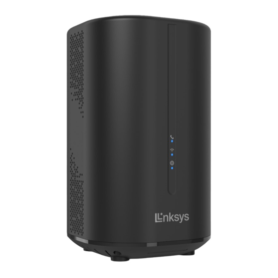
Introduction Product Overview ○ 6 FXS Port ○ 1 Power Input ○ 7 WPS button ○ 2 Power on/off Switch ○ 8 SIM Slot ○ 3 2.5GbE LAN Port ○ 9 Reset button (press 5 sec for reset to ○ 4 1GbE LAN Port default) ○... -
Page 4: Led Indicators
LED Indicators LED Indication Color Status Description Bottom LED - Blue 5G (SA/NSA) On Device connects to 5G network 5G/LTE/3G/Ethernet Green LTE/3G On Device connects to LTE/3G network Wan/Alarm Orange Ethernet WAN Device connects to Internet via Ethernet WAN Alarm System Alarm ON •... - Page 5 Installation Please follow the steps below to install the router: Step1: Insert SIM card into the router with direction shown below until it clicks. Step2: Connect one of the LAN ports (any will do) on the router to your PC with a RJ-45 Ethernet cable provided.
-
Page 6: Web Interface
Note: 1. To remove the SIM card, press the card in until it clicks and it will pop out automatically. 2. 5G/LTE signal strength can be referred on Web GUI, five bars ( ) ON means the strongest signal while one bar ( ) ON means the weakest signal that your device received. - Page 7 Configuration Page” to see the complete settings or tweak the configuration. Detailed information about this page will be stated below Brief Summary Page After login, users can see a “Brief Summary Page” about all functions of FGW5500, each Brief Summary Page block is a link to “Detailed Configuration Page”.
-
Page 8: Detailed Configuration Page
Detailed Configuration Page After clicking any block in “Brief Summary Page”, the webpage would be switched to the “Detailed Configuration Page”. (Take “Mobile Network” block for example) Detailed Configuration Page Main Menu Show the current main menu Sub Menu Clickable, can jump to another Sub Menu under the same Main Menu... -
Page 9: Status | Device Status
Status | Device Status Status > Device Status Host SSID: As titled. Guest SSID: As titled. Firewall: Three possible states, LOW Filtering (Filtering Disabled), Medium (Standard) and High. UPnP: Possible states are Enable and Disable. DMZ: Possible states are Enable and Disable. DDNS: Possible states are Enable and Disable. -
Page 10: Status | Modem Status
Status | Modem Status Status > Modem Status Network: Network mode, possible state is 5G/4G, ENDC/4G, 5G, or 4G Connection Status: If CPE anchored to the base station successfully, the status will be Registered. Otherwise, the status will be No Service. Connection Time: As titled. -
Page 11: Status | Network Status
Status | Network Status Status > Network Status Operation Mode: As titled. IPv4: This section shows IPv4 WAN IP Address, Default Gateway, and DNS Servers of NR indoor CPE. IPv6: This section shows IPv6 WAN IP Address, Default Gateway, DNS Servers, LAN Link-Local Address, LAN Prefix Address, Autoconfiguration Type and DHCP Server PD Prefix of NR indoor CPE. -
Page 12: Status | Client List
Status | Client List Status > Client List Connected Devices: It displays that how many clients connected to the CPE, including wired and wireless devices. BLOCK: Click the “BLOCK” button will bock the device immediately. Blacklist: It displays that the devices have been blocked after clicking the “BLOCK” button. Click “UNBLOCK”... -
Page 13: Network
Network The “Network” page allows user to configure network function such as Modem settings, Internet settings, LAN setting, and IPv6 settings. Network | Modem Settings Network > Modem Settings Network Mode: Possible to state 5G/4G, ENDC/4G, 5G, or 4G. The CPE will automatically detect a SIM card for data APN configuration, and it also supports manual mode for configuration, such as authentication methods (NONE, PAP, CHAP) if service required. -
Page 14: Network | Internet Settings
Network | Internet Settings Network > Internet Settings Operation Mode: Possible to state Dynamic IP, PPTP, L2TP, or IP Passthrough. Dynamic IP: The CPE behaves as DHCP client and receives WAN IP address from core network automatically. - Page 15 PPTP: A Virtual Private Network (VPN) protocol that uses a TCP control channel and a Generic Routing Encapsulation (GRE) tunnel to encapsulate PPP packets. Default Gateway, Server IP Address and login credential are required to input. L2TP: A layer 2 Virtual Private Network (VPN) protocol that uses encryption for its own control messages.
-
Page 16: Network | Lan Settings
Network | LAN Settings Network > LAN Settings LAN Setting: LAN IP Address / LAN IP Subnet Mask: The IP address and subnet mask used by CPE in LAN Ø If users choose other tunnel mode, this IP means LAN side domain and Web GUI IP addres s. -
Page 17: Network | Ipv6 Settings
Network | IPv6 Settings Network > IPv6 Settings The “IPv6” page allows user to get IPv6 information such as WAN Connection Type and WAN IPv6 Address. IPv6 Type: Show IPv6 Connection Type with “Auto Configuration (SLAAC/DHCPv6). DNS Server Source: Get DNS from Auto or Static Autoconfiguration Type: Choose different configuration to assign IPv6 address IPv6 SLAAC DHCPv6 RA Lifetime (seconds): Set DHCPv6 renew time, default setting is 28800 seconds. -
Page 18: Wifi
WiFi In WiFi main menu, you can display and configure WiFi settings. Users can see SSID, current channel and working mode as well as configure wireless setting, security, and access control list. WiFi |Basic WiFi > Basic Enable SSID: As titled. Network Name (SSID): SSID (service set identifier) is a label representing wireless AP. - Page 19 TKIP/AES Key Pass Phrase CCMP Wi-Fi Protected Setup (WPS)– TKIP/CCMP Enable WPS WPA2/WPA3-Personal Pre-shared Settings - CCMP Mixed Mode Key Pass Phrase Pre-shared Settings - TKIP/AES Rekey Interval WPA/WPA2-Personal TKIP Key Pass Phrase Mixed Mode Wi-Fi Protected Setup (WPS)– Enable WPS (only for AES and TKIP/AES.) Guest Network: The separated WiFi network can isolate all of your home devices and services from a “Guest”, which only provides access to the Internet but not to your home network.
-
Page 20: Wifi | Advanced
WiFi | Advanced WiFi > Advanced Working Mode: • 2.4GHz WiFi: There are “802.11 b/g/n/axg”, “802.11 b/g/n”, “802.11 b/g”, and “802.11b”. • 5GHz WiFi: There are “802.11 a/an/ac/axa”, “802.11 a/an/ac”, “802.11 a/an”, and “802.11a”. Bandwidth: The setting is only available when the wireless protocol is used; select the bandwidth from the drop-down list. - Page 21 Cancel button Reset fields to the last saved values. Commit the changes made and save to the CPE device, some Apply button services will be reloaded. If you select “WhiteList” and have no MAC address in the list, no one can establish the connection.
-
Page 22: Wifi | Wps
WiFi | WPS WiFi> WPS Wi-Fi Protected Setup (WPS) Enable WPS: User can share their WiFi via WPS when this box is checked. This feature support for both 2.4GHz and 5GHz radios. WiFi | Connected Client WiFi > Connected Client Host: It displays that how many clients connected to the CPE through both 2.4GHz and 5GHz radios. -
Page 23: Voice | Voice Setting
Voice | Voice Setting Voice > Voice Setting Service Domain: VoIP Registration: This part includes “Account” for validation and “Server Settings” for services configuration. Account: Username, User Account, Password, Password Confirm and Display Name are for VoIP service registration. It requires to contact your service provider to get the credentials. Server Settings: Contact with your service provider to get the right configurations on IP Version, User Domain, Registrar Address, Outbound Proxy Address, Registrar Port, Outbound Proxy Port, RTP Port Range Start and RTP Port Range End. -
Page 24: Advanced | Mac Filtering
Advanced | MAC Filtering Advanced > MAC Filtering MAC Filtering Mode: Users can block or allow clients with certain MAC addresses to access to CPE. Disable: Any clients can establish the connection. Blacklist: Only clients with MAC addresses in “Access Control List” will be blocked, other clients can establish the connection. -
Page 25: Advanced | Ip Filtering
Advanced | IP Filtering Advanced > IP Filtering IP Filtering Mode: Users can block or allow clients with certain IP addresses to access to CPE. Disable: Any clients can establish the connection. Blacklist: Only clients with IP addresses in “Access Control List” will be blocked, other clients can establish the connection. -
Page 26: Advanced | Dynamic Dns
Advanced | Dynamic DNS Advanced > Dynamic DNS Enable DDNS: Users can enable or disable the Dynamic DNS service by clicking the check box. Service Provider: Select either dyndns, noip or ChangeIp as the Dynamic DNS service provider for the CPE. Username: Dynamic DNS service login credential. -
Page 27: Security
Security The “Firewall” page allows user to configure firewall to block and grant some network access. Security | Firewall Security > Firewall Firewall Level: Three possible states, LOW Filtering (Filtering Disabled), Medium (Standard) and High. Prevent DoS Attack: Enable (checked) this feature will prevent the CPE avoid DoS attack. Block Anonymous Internet Requests: Enable (checked) this feature will block someone unknow to request Internet access. -
Page 28: Management
Management The “Management” page allows user to configure the main system parameters such as password, language, device time/name …etc. Management | Configuration Select Management > Configuration to go back to the factory default settings. Restore Factory Settings: Click “Restore Factory Settings” button to clear all users’ configuration and restore to factory default settings. - Page 29 Management | Device Settings Management > Device Settings The Device Settings page lets you change the default username and password. The minimum length of a password shall be 10, and shall meet all 4 of the following 4 complexity rules: Minimally 1 uppercase character (A-Z) Minimally 1 lowercase character (a-z) Minimally 1 digit (0-9)
- Page 30 Timeout/Refresh Setting Management Session Timeout: Automatic logout after the period. (Range: 0-10 Minutes; 0 Ø means never expired) GUI Refresh Time: When users press “auto” button in any page, the page refresh in every Ø designated time. (Range: 5-60 Seconds) Device Time Settings: To enable NTP server for system time synchronization.
-
Page 31: Management | Software
After pressing the “Upgrade” button, it will automatically reboot the CPE and upgrade the firmware with the specified file. You will be prompted to re-login to the CPE after the upgrade is complete. FOTA: Click ”Check New Version” button to get the latest firmware from Linksys cloud server. -
Page 32: Management | Diagnostics
Management | Diagnostics Management > Diagnostics Use system Diagnostics tools to set up parameters such as Diagnostics Type, Protocol Type, Ping Count, Packet Size, Ping Timeout, and get the Diagnostic Result afterward. Diagnostic Tool: Select Ping or Traceroute to check network connectivity. IP Address/Domain Name: Enter the destination to check the CPE connectivity by IP address or Ø... -
Page 33: Specification
Specification Ø Support 5G NR Sub 6GHz for both TDD & FDD 5G NR TDD Bands : n40/n41/n77/n78/n79* 5G NR FDD Bands : n1/n3/n5/n7/n8/n28/n71 Ø Support LTE TDD B38/B40/B41 FDD B1/B3/B7/B8/B20/B28 Ø Support USIM card Ø Web-based configuration Ø Support 1 RJ-11 FXS Port Ø...
Need help?
Do you have a question about the FGW5500 and is the answer not in the manual?
Questions and answers