
Related Manuals for SENSECAP S-RJY-01


Summary of Contents for SENSECAP S-RJY-01
- Page 1 User Manual Dissolved Oxygen Sensor - User Manual Model: S-RJY-01 Version: V1.0 第 1 页 共 14 页 ©2008-2023 Seeed Technology Co., Ltd. All rights reserved. www.seeedstudio.com...
-
Page 2: Table Of Contents
User Manual Table of contents Background meaning and working principle ....................... 3 Background meaning ..........................3 Working principle ............................ 3 Technical Parameters ............................4 Dimensions ................................5 Product installation and wiring ..........................6 RS485 communication............................7 Frame format ............................8 Register address ............................ -
Page 3: Background Meaning And Working Principle
Working principle S-RJY-01 integrated online fluorescence method dissolved oxygen sensor is designed based on the principle of quenching excitation fluorescence by specific substances in physics. When the excitation light is irradiated on the fluorescent substance on the surface of the fluorescent film head, the fluorescent substance is excited and emits fluorescence, and the extinguishing time of the fluorescence is affected by the concentration of oxygen molecules on the surface of the fluorescent film head. -
Page 4: Technical Parameters
User Manual 2. Technical Parameters Model S-RJY-01 Measuring principle Fluorescence Measuring range 0~20.00mg/L (0~200% saturation, 25℃) ±2%F.S., ±0.3℃ Precision 0.01mg/L, 0.1℃ Resolution Two-point calibration Calibration method Temperature Automatic temperature compensation (Pt1000) compensation RS-485(Modbus/RTU) Output method 0~50 ℃, <0.2MPa Operating conditions -5~65℃... -
Page 5: Dimensions
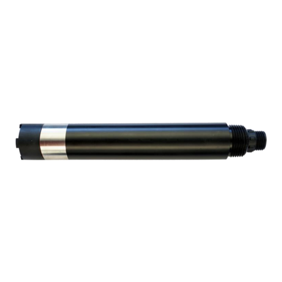
User Manual 3. Dimensions Note: The size sensor connector is a male M16-5 core waterproof connector. 第 5 页 共 14 页 ©2008-2023 Seeed Technology Co., Ltd. All rights reserved. www.seeedstudio.com... -
Page 6: Product Installation And Wiring
User Manual 4. Product installation and wiring The sensor should be submerged below the liquid surface for fixed installation. Avoid bumping or scratching the surface of the fluorescent film head during installation and use. The fluorescent film head part should be prevented from being attached to the bottom sediment. The rubber boot should be removed when in use. -
Page 7: Rs485 Communication
User Manual 5. RS485 communication The Modbus protocol is a common language used in electronic equipment. Through this protocol, network communication is carried out between devices. It has become a common industry standard and is widely used in data collectors, sensor equipment, etc. Based on this protocol, devices produced by different manufacturers can communicate with each other for system integration. -
Page 8: Frame Format
User Manual Frame format 1. Read data instruction frame: xx xx xx xx xx xx CRC check number of address function code register address code (low byte registers first) 2. Read data response frame: xx xx xx xx xx xx Check code address function code... -
Page 9: Register Address
User Manual Register address Register Number of address Name Description Method registers (DEC/HEX) Write data 1 when power on, write data 44353 switch machine 0 when power off. The power-on default 1 (2 bytes) Write (0x1100) is the power-on state. 4 double-byte integers, which are the measured value, the decimal place of 40001... - Page 10 User Manual The calibration value is restored to the default value, and the written data is 0. 48225 reset sensor Note: After the sensor is reset, it needs 1 (2 bytes) Write (0x2020) to be calibrated again before it can be used.
-
Page 11: Command Example
User Manual Command example 1. Boot command: Function: Let the sensor emit light continuously and start measuring the dissolved oxygen value. Request frame: 06 06 11 00 00 01 4C 81 Response frame: 06 06 11 00 00 01 4C 81 2. -
Page 12: Error Response
User Manual Error response If the sensor cannot execute the host computer command correctly, it will return information in the following format: definition address function code CODE CRC check data ADDR COM+80H CRC16 Bytes (1) CODE: 01 - wrong function code 03 - data error (2) COM: Received function code 第... -
Page 13: Use The Serial Port Debugging Software To Communicate
User Manual Use the serial port debugging software to communicate Users can use any serial port debugging software to communicate with the sensor. Pay attention when communicating, select the correct serial port, baud rate, and other serial port communication parameters, and the data that needs to be sent and received must be transmitted and displayed in hexadecimal . -
Page 14: Maintenance
User Manual 6. Maintenance Use and Maintenance Operation Recommended maintenance Wash it every 30 days Cleaning sensor probe Check the sensor and fluorescent film Check it every 30 days heads for damage Replace the fluorescent film head Replace it 1~2 years Calibrating sensor 3~6 months ⚫...
Need help?
Do you have a question about the S-RJY-01 and is the answer not in the manual?
Questions and answers