Table of Contents
Advertisement
Quick Links
Advertisement
Table of Contents

Subscribe to Our Youtube Channel
Related Manuals for Syqwest Bathy 2010PC


Summary of Contents for Syqwest Bathy 2010PC
- Page 1 Bathy 2010PC™ CHIRP Sub Bottom Profiler and Bathymetric Echo Sounder • Installation • Operation • Maintenance SyQwest, Inc. ver. 01.18.11 222 Metro Center Blvd. | Warwick, RI 02886 USA TEL: (401) 921-5170 / FAX: (401) 921-5159 Email: tech-support@syqwestinc.com http://www.syqwestinc.com...
-
Page 3: Table Of Contents
BATHY - 2010 Operations Maintenance Manual TABLE OF CONTENTS 1.0 Introduction ....................1-1 1.1 Safety................................... 1-1 1.2 List of Additional Items .............................. 1-2 1.3 Shipping and Handling..............................1-2 1.4 Emergency Operation and Shutdown .......................... 1-2 2.0 System Overview .................... 2-1 2.1 Bathy 2010 Data Acquisition and Playback ........................ - Page 4 6.2.3 Trace Identification Header..........................6-11 6.3 Navigation Input................................ 6-11 6.4 Heave Data ................................6-13 7.0 Equipment Specifications ................7-1 7.1 Bathy 2010PC Specifications ............................7-1 8.0 Maintenance....................8-3 8.1 POST (Power On Self Test) ............................8-3 8.2 Firmware Update................................. 8-3 8.3 Firmware Update Connection............................
- Page 5 Figure 5-3 SEG-Y Data Collection Screen ........................5-28 Figure 5-4 External Sync Wiring............................. 5-32 Figure 7-1 Bathy 2010pc Dimensions ..........................7-2 Figure 8-1 TRANSDUCER IMPEDANCE TEST DIAGRAM ..................8-5 Figure 9-1 Typical Over the Side Mount (reference drawing) ....................9-3 Figure 9-2 Over The Side Transducer Mounting Picture ......................
- Page 6 BATHY - 2010 Operations Maintenance Manual...
-
Page 7: Introduction
RESUSCITATION - Personnel working with or near high voltages should be familiar with modern methods of resuscitation. The following WARNINGS appear in the text of this manual and are repeated here for emphasis: INTRODUCTION 1-1 ©2010 SyQwest Incorporated... -
Page 8: List Of Additional Items
All precautions should be taken to insure no human contact is made to the unit while power is on. Also note, High Voltage may be present until the High Voltage Capacitors discharge. Contact SyQwest support personnel before opening the Sensor unit at any time. -
Page 9: System Overview
Transducers can be selected for over-the-side mounting or hull mounting. Optional hardware features include external storage, Thermal Display Unit (TDU), rack- mount kit, bulkhead mount kit, transducers and transducer mounts. MENU SELECT POWER Figure 2-1 System Component Overview OVERVIEW 2-1 ©2010 SyQwest Incorporated... -
Page 10: Bathy 2010 Data Acquisition And Playback
65 MIPS The Bathy-2010PC design utilizes an extremely flexible DSP architecture. This benefits the user by allowing them the ability to alter many of the Bathy- 2010PC transmit/receive signal processing characteristics to achieve the optimum system performance for a wide range of applications. OVERVIEW 2-2 ©2010 SyQwest Incorporated... -
Page 11: Dual Channel Power Transmitter
It is rated at a maximum power level of 600 watts at 3.5KHz for a 30% duty cycle (30 degree beamwidth). BATHY-2010 systems use TR-109 transducers in array configurations to provide full power capability for deep water bathymetry and/or sub- bottom profiling. OVERVIEW 2-3 ©2010 SyQwest Incorporated... -
Page 12: Tc-12/34
60 Watts can be necessary. The extra wattage goes to sourcing the power for the Transmitter outputs. The Bathy-2010PC may require a slightly overrated Power Supply that can current limit appropriately to accommodate a short current surge at system power up. OVERVIEW 2-4 ©2010 SyQwest Incorporated... -
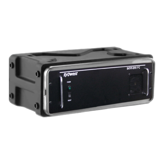
Page 13: System Indicators
BATHY – 2010PC Operations Maintenance Manual Figure 2-2 Bathy-2010pc Rear Panel Connections Figure 2-3 Bathy-2010 Controls And Sysyem Indicators 2.8.1 System Indicators A power indicator light, and power switch are located on the front panel.. OVERVIEW 2-5 ©2010 SyQwest Incorporated... -
Page 14: Table 2-1 Bathy-2010Pc System Cables
In some applications (small boats, temporary installations) the Transducer(s) will have the connector attached to the cable at the SyQwest manufacturing facility, if requested. In more complicated installations, the transducer connectors will be supplied in kits along with optional Junction boxes, and extension cables. - Page 15 The white wire in the power cable OR (BUT NOT BOTH) a ground wire to the unit ground stud is needed. Connecting both the white wire and the ground stud to earth ground may degrade performance due to induced ground loops. OVERVIEW 2-7 ©2010 SyQwest Incorporated...
- Page 16 They are defined as: WHITE (or BLUE)- Transducer + BLACK (or BROWN) - Transducer – GREEN - Transducer Shield The Transducer Connector on the Sensor Unit is shown below in Figure 2-5. Figure 2-5 Bathy-2010PC LF Transducer Connector OVERVIEW 2-8 ©2010 SyQwest Incorporated...
-
Page 17: Host Pc Electrical Connections Gps Connection
Host PC Electrical Connections GPS Connection Connecting a GPS or other Navigation input to the PC running the Bathy-2010PC™ software allows the user to store and annotate Date, Time, Position, and Heading information to the Acoustic data returns. OVERVIEW 2-9 ©2010 SyQwest Incorporated... - Page 18 Hydrographic Software packages (i.e. HyPack, HyDroPro, ..). Printer Connection The Bathy-2010PC PC Software allows the user to interface to the all of the SYQWEST TDU Thermal Printers. The connection is established through the PC’s Parallel Printer Port (25-pin D-Type) as shown below in Figure 2-6. Once the software has been started, all displayed acoustic data can be printed to the TDU in either Acquisition or Playback mode.
-
Page 19: Bathy-2010Pc Pc Software Installation And Host Setup
The InstallShield Wizard will guide you through the next step where you have the option of choosing an install directory. By default, the Bathy-2010PC PC software is installed in the Program Files folder under the sub-directory SyQwest. In the next step, you may choose a Typical, Minimal, or Custom installation. Selecting Typical will perform a complete install of both the Bathy-2010PC application and Sample Data for playback. -
Page 20: Setting Up The Bathy-2010Pc Ethernet Interface
(same as the alternate). If you already use that connection, or you a limited on your network connections, you can select the alternate tab. When selected will be displayed with “Automatic private IP add ress” selected. SOFTWARE AND HOST SETUP 3-2 ©2010 SyQwest Incorporated... -
Page 21: Setting An Alternate Static Ip Address For Network Connection
“alternate” static IP address. The use of the alternate IP address occurs when the computer cannot find a DHCP server such as when it is connected to your Bathy-2010PC. END OF SOFTWARE INSTALLATION SECTION SOFTWARE AND HOST SETUP 3-3 ©2010 SyQwest Incorporated... - Page 22 BATHY – 2010PC Operations Maintenance Manual THIS PAGE INTENTIONALLY LEFT BLANK SOFTWARE AND HOST SETUP 3-4 ©2010 SyQwest Incorporated...
-
Page 23: Theory Of Operation
2 times the transmitted pulse length in value. The average peak value is then used to normalize the detected signal by applying a gain factor which is proportional to the maximum signal level (gain factor=max value/average peak value). This is done dynamically for each processed output sample. THEORY OF OPERATION 4-1 ©2010 SyQwest Incorporated... - Page 24 As in HYDROGRAPHIC mode of operation, the hardware receiver gain is controlled as a function of ambient RMS background noise levels. THEORY OF OPERATION 4-2 ©2010 SyQwest Incorporated...
-
Page 25: Pinger Mode Theory Of Operation
Monitor the returns and note each time the returns cross paths. When the calculated numbers of crossings have been noted monitor the returns and insure that they do not cross path again. Crossing again would indicate that the pinger has hit the bottom. THEORY OF OPERATION 4-3 ©2010 SyQwest Incorporated... - Page 26 BATHY – 2010PC Operations Maintenance Manual THIS PAGE INTENTIONALLY LEFT BLANK THEORY OF OPERATION 4-4 ©2010 SyQwest Incorporated...
-
Page 27: Operation
GPS Position, Time/Date, Ping Count, most used system parameter controls, available disk space (for data storage), and Bathy 2010 Data Acquisition / Playback Unit status. OPERATION 5-5 ©2010 SyQwest Incorporated... -
Page 28: Figure 5-2 Zoom Mode
See the below picture and table for more info. (The picture reflects the software in Zoom mode) Figure 5-2 Zoom Mode NOTE: The current on-screen bottom image in both Zoom and Data windows will be lost upon resizing the window IOPERATION 5-6 ©2010 SyQwest Incorporated... -
Page 29: The Toolbar
Stops the Bathy 2010 Data Acquisition / Playback Unit Pinging Playback a Previously Recorded File Toggle Fast Forward/Normal Playback Pause Playback Stop Playback Playback Slide Bar NOTE: Playback buttons are available in Playback mode only and will be disabled otherwise. OPERATION 5-7 ©2010 SyQwest Incorporated... -
Page 30: Function Key Controls
• F10 – Manual Annotation • F11 – Toggle Auto All Button NOTE: When changing the system parameters press the corresponding Hot Key and use the up/down key on the directional pad to select the desired parameters. IOPERATION 5-8 ©2010 SyQwest Incorporated... -
Page 31: Navigation/Depth Display
For example, consider the following: Bottom Depth is 40.0 meters Range is set to 0 - 80 meters BT Gain is set to 0.5 dB/m Ch. 1 or Optional Ch. 2 Gain is set to 30 dB OPERATION 5-9 ©2010 SyQwest Incorporated... -
Page 32: Range, Zoom Range, And Shift Controls
Bathy 2010 automatically. While the Range control is disabled, it will indicate the current Range setting that the Data Acquisition / Playback Unit has chosen. Shift Range will also not be available nor have any effect in Auto All mode. IOPERATION 5-10 ©2010 SyQwest Incorporated... -
Page 33: Data Acquisition / Playback Unit State
The status shows the drive letter of the destination drive as well as a graph depicting how much free/used space is present on that drive. During recording, the current file size will be shown also. OPERATION 5-11 ©2010 SyQwest Incorporated... -
Page 34: Range Markers
Creates a new file on the specified hard disk for capturing acquisition data. If the Bathy 2010 Data Acquisition / Playback Unit is already pinging, then the software will start the data recording immediately. The filename is based on the system date/time in the following format: IOPERATION 5-12 ©2010 SyQwest Incorporated... - Page 35 - 2-digits Days - 2-digits for Hours - 2-digits for Minutes - 2-digits for Seconds .odc - SYQWEST, INC.’s Proprietary File Extension .seg - Standard SEG-Y format .csv -ASCII file that stores data logger output information NOTE: Once recording is started, this option will become “Stop Recording”.
- Page 36 FM (correlation) or CW (energy detection) processing. The Raw option is used for 16 bit, two’s complement value, directly from the analog to digital converted. Raw reflects the signal that has been amplified and filtered but no DSP process to signal. IOPERATION 5-14 ©2010 SyQwest Incorporated...
- Page 37 The SEGY header is a 40 line, 80 bytes per line, EBCDIC header. The user can enter file information in this text box. There are 37 user lines, which can store up to 76 characters per line. The first three lines are reserved for SyQwest information. Recommended information for the EBCDIC header is:...
-
Page 38: Open For Playback
When used in conjunction with a GPS (the position will be stored in the screen shot as well if a GPS is connected), the exact location, date, and time are all accessible at a moments notice IOPERATION 5-16 ©2010 SyQwest Incorporated... -
Page 39: Recent Files
Selecting this option will allow you to enter a custom text message to be inserted on the display, the recorded file (if recording is on), and if enabled, the thermal printout. In addition, annotation text can also be inserted by clicking the corresponding toolbar button. (See Section 3.1) OPERATION 5-17 ©2010 SyQwest Incorporated... -
Page 40: Configure Acquisition Parameters
Transmit waveform shaping is provided to allow for maximum average power or a reduction in range side lobes, resulting in higher resolution sub-bottom profiles and slope tracking. Selectable windows are: Rectangular, Cosine, Hamming, or Blackman IOPERATION 5-18 ©2010 SyQwest Incorporated... -
Page 41: Configure Serial Ports
Allows the user to select the serial inputs and output as required for Navigation, Data Logging, External Events, Sonar Port and SEGY storage settings. Sonar port must always be enabled for system operation. SEGY must be enabled to permit SEGY storage. Data Logger, Navigation, and External Events are optional. OPERATION 5-19 ©2010 SyQwest Incorporated... -
Page 42: Configure Events
NOTE: Periodic Eventing is not available when External Eventing has been enabled. NOTE: All event marks and text annotation shown on the screen are inserted BETWEEN the acquired bottom data so that there is no loss of information. IOPERATION 5-20 ©2010 SyQwest Incorporated... -
Page 43: Configure Thermal Printer
This menu allows you to configure a thermal printer for use with the Bathy 2010 software. It supports 6 different models from the Raytheon/SYQWEST, INC. TDU series, including the TDU-850, TDU-1200, TDU-2000, TDU-8.5IE and EPC 9800 series and the HSP-100 models. -
Page 44: Configure Gate Limits
Clutter setting from 1 to 9 can be selected to the user liking. Level 1 permits the lowest signal levels to be viewed. The optimum values for most applications are in the 4-6 range. IOPERATION 5-22 ©2010 SyQwest Incorporated... -
Page 45: Configure Draft
5.16.11 Configure Heave When enabled this will compensate for the heave of the vessel and correct the value of the depth being recorded OPERATION 5-23 ©2010 SyQwest Incorporated... -
Page 46: User Preferences
This menu also allows the user select the Alarm Count which is a threshold on which if the bottom is lost for a user selectable number of pings the Bathy 2010 will then signal; bottom lost. IOPERATION 5-24 ©2010 SyQwest Incorporated... -
Page 47: View Menu
NOTE: GUI Zoom does not provide increased data resolution. It simply magnifies the pixels shown in the normal window. To view data with higher resolution Bottom Zoom, Bottom Lock Zoom, or Marker Bottom must be selected during data acquisition. OPERATION 5-25 ©2010 SyQwest Incorporated... -
Page 48: Transmit Mode
There are 4 display modes available with Bathy 2010 software, including 3 Zoom modes, and 1 without any zoom. They include: Normal This mode displays the normal bottom data by itself without any zoom information. When selected, this mode will use the entire viewing area. IOPERATION 5-26 ©2010 SyQwest Incorporated... -
Page 49: Help Menu
Clicking it will display a window with information such as the Bathy 2010’s software version and SyQwest, Inc.’s company information. In addition, the software will request and display Hardware/Firmware version information from the Bathy 2010’s DSP to ensure it is connected and communicating properly. -
Page 50: Figure 5-3 Seg-Y Data Collection Screen
(msec) option in the unit selection box) IOPERATION 5-28 ©2010 SyQwest Incorporated... - Page 51 Bottom Track state has been realized. When in the bottom coast state the digitizer either returns to the bottom track state if a valid bottom is found or transitions to the Bottom Lost state after a designated number of pings. OPERATION 5-29 ©2010 SyQwest Incorporated...
- Page 52 50 msec -> 300 msec (current system only supports 50 msec and 100 msec). Since this parameter is manually selected by the user in all applications, the information above is sufficient to allow the developer to implement the function. Sample Duration Effective Penetration 50 msec 37.5m 100 msec IOPERATION 5-30 ©2010 SyQwest Incorporated...
-
Page 53: Odc To Seg-Y Conversion Tool
The B2010 can support either method of operation but most users have had good success with the simpler method of sonar synchronization. Connection to the Bathy-2010PC is via the rear panel connector J3, refer to Figure 5-4 on following page. OPERATION 5-31 ©2010 SyQwest Incorporated... -
Page 54: Figure 5-4 External Sync Wiring
BATHY – 2010PC Operations Maintenance Manual Figure 5-4 External Sync Wiring IOPERATION 5-32 ©2010 SyQwest Incorporated... -
Page 55: Data Logger) Serial Input/Output Protocol
"F" indicates a Fix Mark. The second character after the “T”, represented above by an f, indicates which frequency return the depth value applies to. “H” indicates a High frequency depth, and “L” indicates a Low frequency depth. SERIAL PROTOCOLS 6-1 ©2010 SyQwest Incorporated... -
Page 56: Nmea Depth Below Transducer (Dbt) Format
5 significant digits to the left of the fixed decimal point and 1 digit to the right units in feet(FT),meters(ME),or fathoms(FA) date tag delimiter MM/DD/YY date in month/day/year format time tag delimiter HH:MM:SS.SS time in hours/minutes/seconds/hundreths format <CR><LF> end of string sequence carriage return/line feed SERIAL PROTOCOLS 6-2 ©2010 SyQwest Incorporated... -
Page 57: All Data Output String (90 Ascii Characters)
X=4 Blackman space delimiter primary transmit frequency X=1 3.5 Khz X=2 12.0 Khz x=3 16.0 Khz or 18 Khz (system dependent) x=4 33.0 Khz or 34 Khz (system dependent) x=5 Dual Channel LO/HI space delimiter SERIAL PROTOCOLS 6-3 ©2010 SyQwest Incorporated... - Page 58 X=3 4 Khz space delimiter transmit power level X=0 0 dB X=4 -24 dB X=8 OFF X=1 -6 dB X=5 -30 dB X=2 -12 dB X=6 -36 dB X=3 -18 dB X=7 -42 dB SERIAL PROTOCOLS 6-4 ©2010 SyQwest Incorporated...
- Page 59 X=ASCII A thru D hydrographic +30 thru + 60 dB manual X=ASCII E thru K sub-bottom 1 thru sub-bottom 7 space delimiter SSSS speed of sound in selected units space delimiter DD.D draft setting in selected units to nearest tenth SERIAL PROTOCOLS 6-5 ©2010 SyQwest Incorporated...
-
Page 60: Depth Only Output String (60 Ascii Characters)
(" " for + heave, "-" for - heave) HHHH heave data in centimeters date tag delimiter MM/DD/YY date in month/day/year format time tag delimiter HH:MM:SS.SS time in hours/minutes/seconds/hundreths format <CR><LF> end of string sequence carriage return/line feed SERIAL PROTOCOLS 6-6 ©2010 SyQwest Incorporated... -
Page 61: All Data Ascii Output String (115 Ascii Characters)
X=3 Cosine X=4 Blackman space delimiter primary transmit frequency X=1 3.5 Khz X=2 12.0 Khz x=3 16.0 Khz or 18 Khz (system dependent) x=4 33.0 Khz or 34 Khz (system dependent) x=5 Dual Channel LO/HI SERIAL PROTOCOLS 6-7 ©2010 SyQwest Incorporated... - Page 62 X=4 50 msec space delimiter system operating mode X=1 CW parametric X=2 CW X=3 FM parametric X=4 FM space delimiter frequency sweep bandwidth X=1 1 Khz X=2 2 Khz X=3 5 Khz space delimiter SERIAL PROTOCOLS 6-8 ©2010 SyQwest Incorporated...
- Page 63 X=0 hydrographic AGC X=1 thru 9 hydrographic +3dB thru +27dB manual X=ASCII A thru D hydrographic +30 thru + 60 dB manual X=ASCII E thru K sub-bottom 1 thru sub-bottom 7 space delimiter SERIAL PROTOCOLS 6-9 ©2010 SyQwest Incorporated...
-
Page 64: Segy File Storage Format
6.2 SEGY File Storage Format 6.2.1 SEGY File Header Information 80 ASCII Bytes per line. All lines are prefixed with ”C nn”. The first three lines are reserved for SyQwest use. End Textual Header Total of 3200 bytes within this header. -
Page 65: Trace Identification Header
Serial Port Configuration Menu under the Navigation tab. PMC, GGA and GLL. The hardware characteristics are the same for all three and are exhibited below: Hardware Characteristics Data Bits Per ACSII Character User Selectable Start Bits User Selectable SERIAL PROTOCOLS 6-11 ©2010 SyQwest Incorporated... - Page 66 $GPGLL,4916.45,N,12311.12,W,225444,A,*31 Where: Geographic position, Latitude and Longitude 4916.46,N Latitude 49 deg. 16.45 min. North 12311.12,W Longitude 123 deg. 11.12 min. West 225444 Fix taken at 22:54:44 UTC Data Active or V (void) checksum data SERIAL PROTOCOLS 6-12 ©2010 SyQwest Incorporated...
-
Page 67: Heave Data
Port Communication menu under the Heave tab and will use the data for depth processing. The serial data format for the motion data output is based on the serial output of a VT/ TSS DMS-5 Roll-Pitch-Heave Sensor. SERIAL PROTOCOLS 6-13 ©2010 SyQwest Incorporated... - Page 68 Don't Cares (Not used by BATHY-2010) Sign of Heave (<SP> if positive, else "-") HHHH Real-Time Heave in CM XXX-->X All X's are Don't Cares (Not used by BATHY-2010) <CR><LF> Carriage Return, Line Feed Record End Characters SERIAL PROTOCOLS 6-14 ©2010 SyQwest Incorporated...
-
Page 69: Equipment Specifications
Maintenance Manual 7.0 EQUIPMENT SPECIFICATIONS The following paragraphs will address the BATHY-2010PC equipment design specifications and operating characteristics. 7.1 Bathy 2010PC Specifications Units Feet or Meters 30, 60, 120, 240, 480, 800, 1500, 2400, 3000, 6000, 15000 Feet Depth Ranges... -
Page 70: Figure 7-1 Bathy 2010Pc Dimensions
BATHY – 2010PC Operations Maintenance Manual Figure 7-1 Bathy 2010pc Dimensions SPECIFICATIONS S 7-2 ©2010 SyQwest Incorporated... -
Page 71: Maintenance
SyQwest’s Support Dept. for assistance. The Sensor may just need to have its flash reprogrammed but SyQwest should be notified anyway. The Bathy-2010PC PC Software will detect a problem with the Sensor as well. The problem will show up on the GUI in the System Status window as a “Sensor State Unknown”... -
Page 72: Firmware Update Process
Maintenance Manual 8.4 Firmware Update Process Get the latest version of the Bathy-2010PC Firmware from SyQwest and copy the file onto the appropriate memory device so it can be accessed by the Bathy-2010PC Host Computer. The format for the file should be as follows: EBOX_V61D.hex. The Firmware Version Number is the “61”... -
Page 73: Transducer Impedance Test
Step 4 Adjust the decade resistor box so that channel B is exactly one half of channel Step 5 Read the value of the decade resistor box. This value is the resistance of the transducer. MAINTENANCE 8-5 ©2010 SyQwest Incorporated... - Page 74 BATHY – 2010PC Operations Maintenance Manual THIS PAGE INTENTIONALLY LEFT BLANK MAINTENANCE 8-6 ©2010 SyQwest Incorporated...
-
Page 75: General Information
In addition, there should be sufficient room to permit use of the necessary tools to facilitate the installation-mounting requirements. Ideally, the location would provide a relatively direct cable run to the site of the Bathy-2010PC Sensor Unit. GENERAL INFO, TRANSDUCERS A 9-1 ©2010 SyQwest Incorporated... -
Page 76: Handling Transducers
Also, when handling the transducer, avoid lifting or pulling on the transducer cable. Although the cable appears thick and substantial, the internal cable wiring could be damaged by stress from the sheer weight of the transducer and cause a malfunction at the most inopportune time. GENERAL INFO, TRANSDUCERS 9-2 ©2010 SyQwest Incorporated... -
Page 77: Portable Transducer Installation
Large “C” Clamps to affix the 4x4 across the beam of the vessel User Supplied Protective Pads or Carpet Remnants User Supplied Mild Household Detergent (i.e.,dishwashing liquid) Table 9-1 Portable Transducer Installation Parts Figure 9-1 Typical Over the Side Mount (reference drawing) GENERAL INFO, TRANSDUCERS A 9-3 ©2010 SyQwest Incorporated... -
Page 78: Figure 9-2 Over The Side Transducer Mounting Picture
9. Fasten the line(s) or cable(s) fore and aft with sufficient tension to support the pipe when the boat is underway. GENERAL INFO, TRANSDUCERS 9-4 ©2010 SyQwest Incorporated... -
Page 79: Portable Transducer Maintenance
In any permanent installation the intended final configuration should be tested before it is implemented, if possible. For more information regarding the installation of a Seachest or other permanent transducer mount, refer to our website at http://www.syqwestinc.com, or contact us directly. GENERAL INFO, TRANSDUCERS A 9-5 ©2010 SyQwest Incorporated... - Page 80 BATHY – 2010PC Operations Maintenance Manual SYQWEST, INC. http:www.syqwestinc.com tech-support@syqwestinc.com END OF MANUAL GENERAL INFO, TRANSDUCERS 9-6 ©2010 SyQwest Incorporated...
Need help?
Do you have a question about the Bathy 2010PC and is the answer not in the manual?
Questions and answers