Table of Contents
Advertisement
SYQWEST INCORPORATED
High Resolution Echo Sounders and Acoustic Systems
For Precision Seafloor Exploration
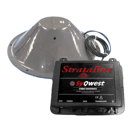
StrataBox™ Marine
Geophysical Instrument
• Installation
• Operation
• Maintenance
ver 08.25.06a
222 Metro Center Blvd. * Warwick, Rhode Island 02886
Tel: (401) 921-5170 * FAX: (401) 921-5159
Website
http://www.syqwestinc.com/
Email:
mailto:tech-support@syqwestinc.com
Advertisement
Table of Contents

Subscribe to Our Youtube Channel
Related Manuals for Syqwest StrataBox


Summary of Contents for Syqwest StrataBox
- Page 1 SYQWEST INCORPORATED High Resolution Echo Sounders and Acoustic Systems For Precision Seafloor Exploration StrataBox™ Marine Geophysical Instrument • Installation • Operation • Maintenance ver 08.25.06a 222 Metro Center Blvd. * Warwick, Rhode Island 02886 Tel: (401) 921-5170 * FAX: (401) 921-5159 Website http://www.syqwestinc.com/...
- Page 3 The Stratabox is intended for use in shallow water. Unfortunately, using low frequency sonar is best for strata penetration but it also makes for significant surface reverberation and multiple echo issues.
- Page 4 3) Long and Lat and Depth window cursor "mouse over display". 4) .odc to SEG-Y (.seg) file converter. Select from Tools pull-down menu. 5) .odc to SEG-Y (.seg) multi-file batch converter. Select from Tools pull-down menu. Useful for Stratabox customers who have many .odc files to convert.
- Page 5 USB to serial adapters but overall most customers have had bad (or no) luck with them. Also, please be advised that the Stratabox data cable with built in RS422 (Stratabox end) to RS232 (computer end) converter needs to be a direct connection to a COM port to insure consistent two-way communication.
- Page 6 Click the yes button and it will update the flash memory device on the DSP. 6. When the update is completed cycle power on the Stratabox and you should see a flashing green light.
- Page 7 2. Install the new version of Stratabox software provided. 3. Connect the Stratabox 3510 with power applied to the Stratabox with data cable to the com port you assigned and connect the data cable to the 10kHz data cable connector.
- Page 8 8 where COM 5 is A, COM 6 is B etc. 2. Connect Interface cable to 4 port cable and equipment as shown in Figure 4-1. 3. In Stratabox software, select EDIT from taskbar then “Configure Sonar Port”. Select COM port Windows assigned for connector A.
-
Page 11: Table Of Contents
StrataBox Sensor Specifications ..................1-7 2.0 INSTALLATION..........................2-1 ..............2-1 TRATA YSTEM NSTALLATION VERVIEW 2.1.1 - Getting Started........................2-2 2.1.2 - Installing the StrataBox Electronics ................2-3 2.1.3 - Installing the StrataBox Transducer................2-5 2.1.4 - Electrical Connections....................2-11 PC S .................2-14 TRATA OFTWARE NSTALLATION 3.0 OPERATION .............................3-1 PC S ......................3-1... - Page 12 Figure 2-3 Transducer Mounting Ring....................2-7 Figure 2-4 Over The Side Transducer Mounting..................2-8 Figure 2-5 StrataBox Sensor Unit Connections...................2-11 Figure 2-6 StrataBox Sensor Power Connector ..................2-12 Figure 2-7 StrataBox Sensor Data Connector ..................2-13 Figure 2-8 StrataBox Sensor Transducer Connector .................2-13 Figure 2-9 Printer Port .........................2-14 TABLE OF TABLES Table 2-1 Basic Equipment ........................2-2...
-
Page 13: Introduction
StrataBox Sensor device. It will also include this manual in PDF format and any Release Notes that have been generated. A hardcopy of the StrataBox™ Manual is also included so that the user may learn to install, operate, and maintain the StrataBox™ Equipment and Accessories. The manual also includes a section on acoustic theory. -
Page 14: Echo Sounding Principles
STRATABOX ™ Operations And Maintenance Manual 2) Installation, which provides details on how to properly mount all of the StrataBox System components. Details on installing the StrataBox PC Software package are included also. 3) Operational instructions describing how to operate the StrataBox Sensor unit and the StrataBox PC Software. -
Page 15: Figure 1-1 Absorption Coefficient Versus Frequency
STRATABOX ™ Operations and Maintenance Manual For echo sounders, the distance actually traveled is two times the distance to the seafloor from the source transducer (from the transmission source, to the bottom and back again). This results in a significant source of signal loss for the system receiving the sound pulse, which must be compensated for at the receiver. - Page 16 STRATABOX ™ Operations And Maintenance Manual Sound reflected off the seafloor usually suffers a significant loss in intensity. Part of this loss is due to scattering (reflection) but most of it results from the portion of sound entering the new medium and traveling into the seafloor until it is completely absorbed.
- Page 17 STRATABOX ™ Operations and Maintenance Manual Cavitation is a result of the pressure on the face of the transducer reducing to a level that permits the water to boil (i.e. turn from a liquid to a gas). This is directly related to the flow around the transducer as described above.
-
Page 18: Figure 1-2 Acoustic Beam Pattern
STRATABOX ™ Operations And Maintenance Manual Beam Width The beam width of a transducer is described as the width of the main lobe of a transmit pattern. The width is usually measured between the -3 dB points on either side of the beam pattern. Shown in Figure 1-2 is a transmit beam pattern for a 125 kHz transducer. -
Page 19: Specifications
NMEA 0183, GLL, GGA, RMC, VTG, VHW, HDT Geographic Position Selectable Baud Rates (RS-232): 4800, 9600, 19200, 38400 Data Interface SYQWEST StrataBox Interface, 57600 Baud (RS-422) Printer Output Centronics (Parallel Port) interface to TDU Series Thermal Printers Shallow Water < 2.5 Meters; bottom type dependant... - Page 20 STRATABOX ™ Operations And Maintenance Manual THIS PAGE INTENTIONALLY LEFT BLANK INTRODUCTION 1-8 ©2006 SyQwest Incorporated...
-
Page 21: Installation
StrataBox. A summary is given of the software installation and setup procedure as well. Although the StrataBox Sensor is designed to deliver the highest levels of quality and performance, it can best attain those standards when the equipment has been properly installed. Because of the great variety of vessels that will employ the StrataBox Sensor, it is not feasible to provide complete and detailed instructions that will fit all installation possibilities. -
Page 22: Getting Started
Verify that all parts described in the next section have been shipped with the unit. Basic Equipment The following (Table 2-1) is a list of the basic equipment supplied with the StrataBox Geophysical Instrument (P04400): Part... -
Page 23: Installing The Stratabox Electronics
The StrataBox Sensor Unit is designed for portable, marine applications but maybe used in permanent installations as well. The user must determine if the StrataBox Sensor Unit is to be mounted on the vessel or just placed in a convenient place on-board the vessel. Either way the appropriate location for the unit needs to be determined. - Page 24 4. Environmental. The operating temperature of the StrataBox Sensor is –25C to +60C thus the operating temperature range of the PC is likely the limiting factor for temperature. The unit has also passed all of the EN60945 emission tests (radiation and immunity).
-
Page 25: Installing The Stratabox Transducer
2.1.3 - Installing the StrataBox Transducer General Transducer The StrataBox is equipped with a single lightweight, Line-in-Cone transducer that is designed for portable, over-the-side mount applications. It may also be used in permanent installations but will need to be mounted in a water filled seachest in those installations. Before installing the transducer, the installer should read and understand the appropriate section below to insure that all of the installation issues are considered. - Page 26 Handling Transducers The transducer is the heart of the StrataBox system and, in spite of its appearance and size, is a delicate instrument. Although it is designed to be in contact with and survive tough marine environments, it should not be dropped or mishandled during the installation.
-
Page 27: Figure 2-3 Transducer Mounting Ring
Portable Transducer Installation Portable installations of the StrataBox transducer for most survey vessels will be of the over-the-side pipe mount type. This type of installation is achieved with the following list of materials:... -
Page 28: Figure 2-4 Over The Side Transducer Mounting
STRATABOX ™ Operations And Maintenance Manual Refer to Figure 2-4 below while reading and implementing the Installation procedure listed below. Figure 2-4 Over The Side Transducer Mounting INSTALLATION 2-8 ©2006 SyQwest Incorporated... - Page 29 For some applications it may be necessary and/or convenient to mount the StrataBox Transducer permanently in the hull of the vessel. Due to the construction of the StrataBox Transducer it may NOT be directly affixed to the hull of the vessel. A Seachest Installation is required. Guidelines for performing a Seachest installation are described in the following sections.
- Page 30 STRATABOX ™ Operations And Maintenance Manual Seachest Transducer Installation Interior Seachest installations are best suited for solid fiberglass hulls to permit a minimum attenuation of acoustic reply signals. Hulls of other type material types may be considered but most other hull types will require that a Seachest design be built into the hull with an acoustic window across the face of the enclosure (i.e.
-
Page 31: Electrical Connections
There are 3 connections that need to be made to the StrataBox Sensor Unit and the PC for the system function properly. The user also has the option of connecting a GPS input and/or a Thermal Printer. The sections below describe the connection details for each. -
Page 32: Figure 2-6 Stratabox Sensor Power Connector
10-30VDC and is capable of providing 8 watts of power to the unit. Although the StrataBox Sensor unit is reverse polarity and over-voltage protected, it is always required that the power mains be turned off during system wiring for both personal and equipment safety. -
Page 33: Figure 2-7 Stratabox Sensor Data Connector
Data Interface Connection The Data Interface cable supplied with the StrataBox is 10 feet long. It includes 8 conductors and an RS- 422 to RS-232 conversion block. This block connects directly to the COM port of the PC and derives its input power from the DTR and/or RTS signal lines from the PC. -
Page 34: Stratabox Pc Software Installation
COM port that is software selectable by the user. When selecting a PC to use with the StrataBox system the user should insure that PC hardware supports 2 COM Ports if a Navigation input is desired (the StrataBox Sensor/PC interface requires 1 COM port). - Page 35 Also, once the installation is complete, you can check the Launch the program box to execute the StrataBox software as soon as you close the installer. If not, you can run the StrataBox PC software by using the Windows Start button to find the StrataBox menu under Programs, or simply double-click on the StrataBox icon located on your Desktop.
- Page 36 STRATABOX ™ Operations And Maintenance Manual THIS PAGE INTENTIONALLY LEFT BLANK INSTALLATION 2-16 ©2006 SyQwest Incorporated...
-
Page 37: Operation
StrataBox. 3.1.1 - The Main Window The StrataBox Main interface is divided into two fields, the Controls and Status field, and the Data field. The vertical window boundary between the fields may be positioned by the user as desired. - Page 38 GPS (See “Configure NMEA I/O” in Section 3.1.2.1 for more information). Position info is also provided when a GPS receiver is connected to the PC and the StrataBox Software is configured and receiving valid GPS data. When GPS Position data is not available, the display will show “Latitude N/A”...
- Page 39 The Gain controls consist of 2 pull-down menus which control the StrataBox Sensor’s gain settings. The StrataBox Hardware gain is controlled by the DC Gain control and can be set either from 0-75 dB, or to Auto Mode. The BT Gain controls the Bottom Triggered gain which allows the user to amplify acoustic returns in the sub-bottom sediments.
- Page 40 6. Color Palette and Unit Controls The StrataBox PC Software allows you to choose from 4 standard color palettes by clicking on one of the radio buttons located in the Color Control section. If you wish to create your own palette, you can do so by selecting Custom and clicking on the button to right of it.
-
Page 41: The Menu Bar
9. Mouse Depth Fields These fields are where the actual echo return data appears in the StrataBox PC Software. By using the mouse, the user may obtain a digital depth value anywhere in the water column by pointing the mouse cursor and clicking the left mouse button. - Page 42 Operations And Maintenance Manual Start Recording Creates a new file on the specified hard disk for capturing acquisition data. If the StrataBox Sensor is already pinging, then the software will start the data recording immediately. The filename is based on the date/time in the following format: <path>YYYYMMDDhhmmss.odc...
- Page 43 Both the GPS NMEA 0183 and NMEA Depth Out functions operate on the one COM port chosen by the user. An adapter from SYQWEST may be required to use both functions simultaneously. Using the “Enable Serial IO” checkbox, you can enable/disable NMEA Input/Output.
- Page 44 “Periodic Eventing” allows the StrataBox software to insert events at a specific interval, depending on the number of minutes entered by the user. While in periodic mode, the user may still insert manual event marks in addition to the periodic ones.
- Page 45 Configure Thermal Printer This menu allows you to configure a thermal printer for use with the StrataBox software. It supports 3 different models from the Raytheon/SYQWEST TDU series, including the TDU-850, TDU-1200, and the TDU-2000.
- Page 46 The StrataBox software stores recorded data files in the same directory as the application by default, however, you can select an alternate location by clicking the “Browse” button and specifying another directory.
-
Page 47: The Edit Menu
Clicking one will immediately begin playback of the file. Exit You can exit the StrataBox PC Software by either using the “Exit” on this file menu, or by simply clicking on the windows default close button. 3.1.2.2 – The Edit Menu... - Page 48 Normal data (assuming the zoom range is smaller than the normal range). There are 4 display modes available with StrataBox software, including 3 Zoom modes, and 1 without any zoom. They include: Normal This mode displays the normal bottom data by itself without any zoom information.
-
Page 49: The Help Menu
3.1.2.4 – The Help Menu This menu includes a software Help guide along with an About StrataBox option. Clicking it will display a window with information such as the StrataBox software version and SYQWEST company information. In addition, the software will request and display Hardware/Firmware version information from the StrataBox Sensor providing the Sensor is connected and communicating properly. -
Page 51: Maintenance
4.0 MAINTENANCE – POST (Power On Self Test) Each time power is applied to the StrataBox Sensor, it performs a series of self-tests to ensure that it is working optimally. The tests occur as follows: Test 1 – Initialization Test Checks overall functionality of the sensor hardware to verify it is operational. -
Page 52: Connection
This file should always be COPIED from the disk to the PC rather than being moved. This allows the user to retain a copy of the file on disk for backup purposes. Before copying the file, the StrataBox PC Software should NOT be running. The file should be copied to the same directory as the StrataBox executable file. -
Page 53: Troubleshooting
“Sonar Port” menu communication with PC software correct COM port 3) Contact SYQWEST Support 3) Flash Memory is corrupt Dept for assistance 4.4.2 – StrataBox PC Software Troubleshooting Symptom Possible Cause Solution 1) Check connections between PC and Sensor 2) Make sure the Sensor’s LED... - Page 54 STRATABOX ™ Operations And Maintenance Manual OPTIONAL EXTERNAL INTERFACE CONNECTIONS Figure 4-1 Optional Interface Connections END OF MANUAL MAINTENANCE 4-4 ©2006 SyQwest Incorporated...
Need help?
Do you have a question about the StrataBox and is the answer not in the manual?
Questions and answers