Advertisement
Quick Links
Advertisement

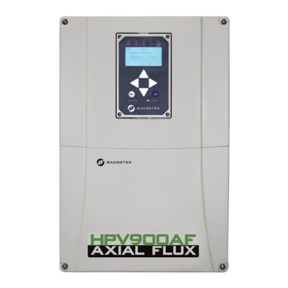
Summary of Contents for Magnetek Elevator Axial Flux HPV900 2 Series
- Page 1 Axial Flux Start Guide Guide to set up 900S2 Axial Flux drive...
-
Page 2: Step 1 - Mechanical Mounting
Axial Flux Start Guide This is a quick setup guide to commission the HPV900 Series 2 Axial Flux drive. Step 1 – Mechanical Mounting First the encoder, proximity switch, and rider wheel must be mounted as follows: Fit the Rider wheel (05P00066-0622) to the encoder (Box 05P00057-0112) using the set screw (05P00302-6208). - Page 3 Axial Flux Start Guide Connect Proximity sensor (46S04441-0010) to proximity bracket (43T02814-0030) with the two M12 nuts on the sensor Remove old tachometer or encoder from the machine, and attach the new bracket and encoder to the motor as shown below. The proximity bracket can be rotated to align with target flag The target flag (43T02814-00XX based on which flag best fits) should be positioned on the sheave so that the short edge will face the proximity sensor.
- Page 4 Axial Flux Start Guide Position target flag: Use gap tool to give correct distance between proximity sensor and target flag:...
-
Page 5: Step 2 - Electrical Connection
Axial Flux Start Guide Step 2 – Electrical Connection Connect the encoder and proximity sensor wires to the drive as follows: The wires are labelled, and should be connected into the terminals with the matching numbers in the long green terminal blocks. -
Page 6: Step 3 - Drive Parameters
Axial Flux Start Guide Step 3 – Drive Parameters The following drive parameters should be entered for the Axial Flux drive: Menu Parameter Correct Setting “PM” Drive Mode “Axial-Flux” Encoder Select Motor Rotation See table below Input L-L Volts Enter Line to Line Voltage From Motor Dataplate Rated Motor Power Rated Motor Voltage... - Page 7 Axial Flux Start Guide Step 4 – Alignment and Autotune HF Inject Procedure The drive must determine an encoder offset value before it can turn the motor. The drive will automatically perform a HF inject alignment when it is given a run command and all parameters are entered with no active faults.
- Page 8 Axial Flux Start Guide During Autotune, a slight buzzing noise should come from the motor for approximately half a second and the RUN light will be lit for the duration of the procedure. READY USER FAULT TORQUE LIMIT 10:00 ALARM! AUTOTUNE IS DONE SUBMENU DATA ENTRY...
-
Page 9: Troubleshooting
Axial Flux Start Guide Troubleshooting If any issues are experienced which are not covered by this guide, please refer to the technical manual (TM354) which is available on the Magnetek website. Faults/Alarms/Difficulties Description Solutions Encoder Flt The drive is in a run condition Incorrect Encoder Phasing ... - Page 10 Axial Flux Start Guide Faults/Alarms/Difficulties Description Solutions HIT TORQUE LIMIT The drive has reached its torque Incorrect Encoder Phasing Verify that the encoder (alarm) limit as defined in the A1 menu. phasing is correct. Swap the A and /A wires in TB1-1 and TB1-2 ...
- Page 11 Axial Flux Start Guide Faults/Alarms/Difficulties Description Solutions Once Per Revolution Bump The motor would jerk every time Parameter Setting Verify that the Encoder the target sensor goes pass the proximity switch Pulses (A1) matches the number for Measured PPR NOTE: for MRL setup, use the Z (D1) while the motor is Edge Count (D1) to see when...
- Page 12 Axial Flux Start Guide Faults/Alarms/Difficulties Description Solutions Spd Dev Flt The speed feedback is failing to Encoder Cable not properly properly track the speed grounded Verify encoder cable is Spd Dev Alm reference properly grounded Motor Runaway Condition – (PM) ...
- Page 13 Axial Flux Start Guide Faults/Alarms/Difficulties Description Solutions Z Marker Loss The drive is expecting a signal Proximity Switch Verify that the target back from the proximity switch but doesn’t see any within the sensor is being seen by the expected window.


Need help?
Do you have a question about the Axial Flux HPV900 2 Series and is the answer not in the manual?
Questions and answers