
Related Manuals for IEPC EPC90132

Summary of Contents for IEPC EPC90132
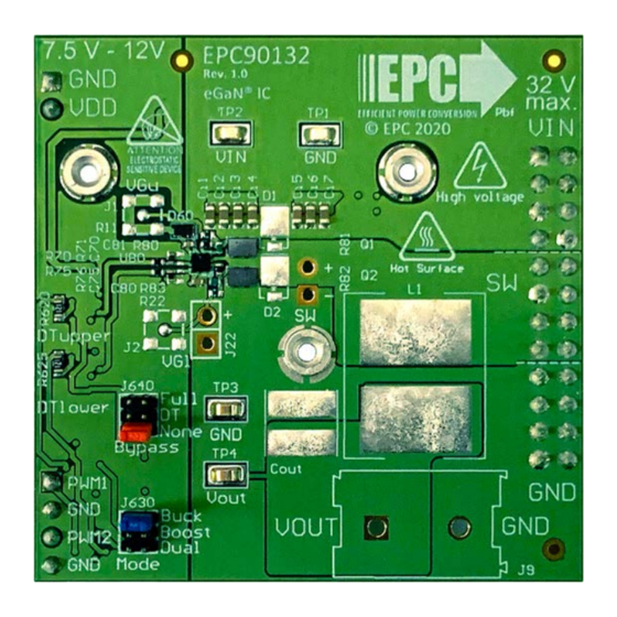
- Page 1 Development Board EPC90132 Quick Start Guide 40 V Half-bridge with Gate Drive, Using EPC2055 Revision 1.0...
- Page 2 EPC2055 GaN FET in a half bridge configuration and one EPC2038 GaN PWM ‘High’ State Input rise and FET used to augment the bootstrap supply. The EPC90132 features the uPI Pulse Width fall time < 10ns Semiconductor uP1966A gate driver. The board also contains all critical PWM ‘Low’...
-
Page 3: Bypass Settings
Boost Dual input The EPC90132 development board is easy to set up as a buck or boost converter to evaluate the performance of two EPC2055 eGaN FETs. This board includes a logic PWM input signal polarity changer used to ensure... - Page 4 QUICK START GUIDE EPC90132 Bypass mode warnings In no-bypass mode, figure 5(a) (red jumper across pins 5 & 6 of J640), both the on-board polarity and dead-time circuits are fully • It is important to provide the correct PWM signals that includes dead- utilized.
- Page 5 QUICK START GUIDE EPC90132 Boost Converter configuration Warning: Never operate the boost converter mode without a Optional anti- Output Capacitor 7.5 –12 V load, as the output voltage can increase beyond the maximum parallel diodes Output Inductor ratings. To operate the board as a boost converter, either a single or dual...
-
Page 6: Measurement Considerations
QUICK START GUIDE EPC90132 MEASUREMENT CONSIDERATIONS Voltage measurement: Input voltage for Buck, Measurement connections are shown in figure 8. Output voltage for Boost EPC90132 Figure 9 shows an actual switch-node voltage HIGH VOLTAGE (HIGH VOLTAGE!) Upper FET Gate measurement when operating the board as a buck Voltage MMCX converter. -
Page 7: Thermal Considerations
EPC recommends t-Global P/N: TG-X 500 µm for the thermal interface material. Figure 10: Details for attaching a heatsink to the EPC90132 board. The mechanical spacers will accept M2 x 0.4 mm (a) 3D perspective, (b) top view details. - Page 8 QUICK START GUIDE QUICK START GUIDE EPC90132 EPC90132 Table 2: Bill of Materials Item Reference Part Description Manufacturer Part Number 1 μF C1608X7R1E105K080AB C60, C61, C81, C610, C611, C612, C614, C615, C616 0.1 μF, 25 V Yageo CC0402KRX7R8BB104 22 nF, 25 V C1005X7R1E223K050BB 4.7 μF, 10 V...
- Page 9 1 F, 25 V Logic Supply 12 VDC 5 V Logic Regulator Stando M2 Stando M2 Stando M2 9774010243R 9774010243R 9774010243R Heatspreader Mount FD 1 FD 2 FD 3 PCB Fi ducial PCB Fi ducial PCB Fi ducial Figure 11: EPC90132 main schematic...
- Page 10 1 F, 50 V 1 F, 50 V 1 F, 50 V 1 F, 50 V 1 F, 50 V 1 F, 50 V 1 F, 50 V DC Input HF Loop Capacitors 32 Vmax. V Gu R 80 100 V, 2 A V GuH V Gu SS2PH 10-M3...
- Page 11 E PC2038 R 60 100 V 2800 m E MPT Y VBSin 5VHS1 Sync Boot = Install R60 and D77, remove R77 No Sync Boot = Install R77, remove R60 and D77 5V 1, 150 mW 0.1 F, 25 V Default = No Sync Boot CD0603-Z5V 1 40 V 30 mA...
- Page 12 JP640 JP630 50mil +Handle R ed V CC 50 mil +Handle Blue V CC J640 F ull By pass SW byp V CC J630 Buck Single Signal PolQlow V CC V CC DT By pass PolQup V CC UseDT V CC Boost Single Signal No By pass Dual...
- Page 13 QUICK START GUIDE EPC90132 U100 MCP1703T-5002E/MC R 100 C101 C100 1 F, 25 V 1 F, 25 V Figure 15: Logic Supply Regulator schematic EPC – POWER CONVERSION TECHNOLOGY LEADER | EPC-CO.COM | ©2021 | | 13...
-
Page 14: Visit Our Website
Demonstration Board Notification The EPC90132 board is intended for product evaluation purposes only. It is not intended for commercial use nor is it FCC approved for resale. Replace components on the Evaluation Board only with those parts shown on the parts list (or Bill of Materials) in the Quick Start Guide. Contact an authorized EPC representative with any questions. This board is intended to be used by certified professionals, in a lab environment, following proper safety procedures.
Need help?
Do you have a question about the EPC90132 and is the answer not in the manual?
Questions and answers