
Related Manuals for Marvel MPDR424IS71A


Summary of Contents for Marvel MPDR424IS71A
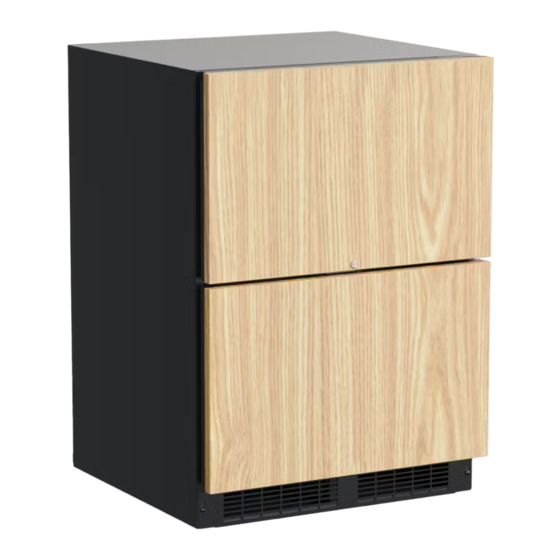
- Page 1 OWNERS GUIDE M ARVEL PROFESSION AL UNDERCOUNTER REFRIGERATION F O R M O D E L # M P D R 4 2 4 T H E O R I G I N A L R E F R I G E R AT I O N E X P E R T S S I N C E 1 8 9 2...
- Page 2 Got a Marvelous Design? The service number and serial number can be found on the We would love to see how your Marvel product looks in its serial plate which is located inside the cabinet on the left new home. Send us photos at marketing@marvelrefrigera- side near the top.
-
Page 3: Table Of Contents
TABLE OF CONTENTS Tip: Click on any section below to jump directly there Safety Control Operation - Service Important Safety Instructions Thermistor Warranty Installation Unpacking Your Appliance Electrical Cutout & Product Dimensions Installing Your Appliance Side-by-Side & Stacking Installations Installing the anti-tip device Drawer Divider Integrated Panel Dimensions Integrated Panel Installation... -
Page 4: Important Safety Instructions Thermistor
IMPORTANT SAFETY INSTRUCTIONS Important Safety Instructions Warnings and safety instructions appearing in this guide are not meant to cover all possible conditions and situa- tions that may occur. Common sense, caution, and care must be exercised when installing, maintaining, or operat- ing this appliance. -
Page 5: Unpacking Your Appliance
UNPACKING YOUR APPLIANCE CAUTION WARNING If the appliance was shipped, handled, or stored in other EXCESSIVE WEIGHT HAZARD than an upright position for any period of time, allow the ap- Use two or more people to move product. pliance to sit upright for a period of at least 24 hours before Failure to do so can result in personal injury. -
Page 6: Electrical
ELECTRICAL Electrical Connection A grounded 115 volt, 15 amp dedicated circuit is required. This product is factory equipped with a power supply cord that has a three-pronged, grounded plug. It must be plugged into a mating grounding type receptacle in accor- dance with the National Electrical Code and applicable lo- Do not remove cal codes and ordinances (see Figure 4). -
Page 7: Cutout & Product Dimensions
CUTOUT AND PRODUCT DIMENSIONS ROUGH-IN OPENING DIMENSIONS CABINET DIMENSIONS MODEL "A" "B" "C" "D" "E" "F" "G" "H" "J" 24" 34-1/4" - 35-1/4" 24" 23-7/8" 33-5/8 - 34-5/8" 23-5/8" 26-1/8" 38-1/4" 41-1/4" MPDR424-S*31A (61 cm) (87 to 89.5 cm) (61 cm) (60.6 cm) (85.4 to 88 cm) (60 cm) - Page 8 CUTOUT AND PRODUCT DIMENSIONS PRODUCT DATA ELECTRICAL PRODUCT MODEL REQUIREMENTS # WEIGHT 140 lbs MPDR424 115V/60Hz/15A (63.6 kg) "G" "D" "F" "E" 1" (2.5 cm) ⁄ " (54.6 cm) Figure 7 "H" Floor mount anti-tip bracket. "I" * To install (F) models with the door face flush with adja- cent cabinetry doors, custom decorative panel thickness cannot exceed ⁄...
-
Page 9: Installing Your Appliance
The over- could result in personal injury. Contact your dealer or all height of your Marvel appliance may be adjusted higher Marvel customer service at 616-754-5601 to order. (by turning the leveling leg out, CCW) and lower (by turning For safety concerns 15"... -
Page 10: Side-By-Side & Stacking Installations
SIDE-BY-SIDE AND STACKING INSTALLATIONS Side-by-Side Installation Hinge-by-Hinge Installation (Mullion) When installing two units hinge-by-hinge, 13/16" (22 mm) Other Site Requirements is required for integrated models. Additional space may be Units must operate from separate, properly grounded elec- needed for any knobs, pulls or handles installed. trical receptacles placed according to each unit's electrical specifications requirements. -
Page 11: Installing The Anti-Tip Device
INSTALLING THE ANTI TIP DEVICE Anti-Tip WARNING Bracket Leveling Leg • ALL APPLIANCES CAN TIP RESULTING IN INJURY. • INSTALL THE ANTI-TIP Bottom View of ⁄ " BRACKET PACKED WITH Beverage (54.6 cm) THE APPLIANCE. Center • FOLLOW THE INSTRUC- TIONS BELOW Front of cabinet Anti-Tip Device... - Page 12 INSTALLING THE ANTI TIP DEVICE NOTE When the floor mounted anti-tip bracket is used the mini- mum adjusted height of the cabinet is increased by ⁄ " (9 mm). "V" notches Rear Leveling leg in bracket Figure 15a Screw ⁄ "...
-
Page 13: Drawer Divider
DRAWER DIVIDER Drawer Divider The top and bottom drawer have an adjustable drawer divider. To adjust the divider, making the 4 areas larger or smaller, move the center post along the length of the rods in either direction. See Figure 16 and 16a. The divider can also be removed from the drawer. -
Page 14: Integrated Panel Dimensions
INTEGRATED PANEL DIMENSIONS 1"(25 mm) diameter counter bore ⁄ " (6 mm) deep 2 places, top drawer only. Panel ⁄ " 19" ⁄ " thickness (60 mm) (483 mm) (603 mm) ⁄ " (30 mm) ⁄ " This side (379 mm) facing interior ⁄... -
Page 15: Integrated Panel Installation
INTEGRATED PANEL INSTALLATION CAUTION It is important to use the factory provided grille that came with the product to assure proper air flow is maintained through the condenser. The use of a custom grille is not recommended and will void the warranty. Full Integrated Panel Installation Instructions Determine Wood Screw Requirements 1. - Page 16 INTEGRATED PANEL INSTALLATION Step 1: Remove Drawers from unit. 1. Begin by pulling out the top drawer. (See Figure 14). .35/.31 Remove screws securing drawer to slides (See Figure (9 mm/7.5 mm) 15). Pull drawer forward, lift up and out to clear clips in rear of drawer.
- Page 17 INTEGRATED PANEL INSTALLATION Step 3: Attach the Integrated Panel to the Drawer 1. Set the integrated panel on drawer front face and align edges. (See Figure 17). The custom integrated panel should be flush with the top of the drawer and centered on the width of the drawer.
- Page 18 Time to reach set point varies based upon ambient temperature, temperature of product loaded, door openings, etc. Marvel recommends allowing the unit to reach set points before loading.
-
Page 19: Care And Cleaning
CARE AND CLEANING Front Grille The following suggestions will minimize the Be sure that nothing obstructs the required air flow open- cost of operating your refrigeration appliance. ings in front of the cabinet. At least once or twice a year, 1. - Page 20 ENERGY SAVING TIPS The following suggestions will minimize the cost of operating your refrigeration appliance. 1. Do not install your appliance next to a hot appliance (cooker, dishwasher, etc.), heating air duct, or other heat sources. 2. Install product out of direct sunlight. 3.
-
Page 21: Extended Non-Use
Winterization If the unit will be exposed to temperatures of 40° F (5° C) or less, the steps above must be followed. For questions regarding winterization, please call Marvel at (616) 754-5601. CAUTION Damage caused by freezing temperatures is not covered... -
Page 22: Obtaining Service
OBTAINING SERVICE If Service is Required: • If the product is within the first year warranty period please contact your dealer or call Marvel Customer Service at 616.754.5601 for directions on how to obtain warranty coverage in your area. •... - Page 23 41015881_A White light (upper & lower) Blue light (upper & lower) Evap fan Evap fan Condenser fan Zone temp Evap temp Zone temp Evap temp Door switch 1 Defrost Heater Door switch 2 Compressor / Condenser Power In N.C. Neutral FUSE...
-
Page 24: Ordering Replacement Parts
Warranty parts will be shipped at no charge after Marvel confirms warranty status. Please provide the model, serial number, part number and part description. Some parts will require color or voltage information. - Page 25 Warranty parts will be shipped at no charge after Marvel confirms warranty status. Please provide the model, serial number, part number and part description. Some parts will require color or voltage information.
-
Page 26: R600A Specifications
PERSONNEL DO HOT PUNCTURE REFRIGERANT TUBING refrigeration system. RISK Of FIRE OR EXPLOSION. FIAMHA_ B LE REFRIGERANT USED. CONSULT Never substitute Marvel OEM replacement parts REPAIR IIANUAVOWHER'S GUIDE BEFORE ATTEMPTING TO SERVICE THIS PRODUCT. ALL SAFETY PRECAUTIONS HUST BE FOUOWEO. - Page 27 R-600A SPECIFICATIONS/LABELING WARNING R-600a equipped products are labeled (both the unit and the compressor). Only skilled and well trained service technicians permitted to service R-600a equipped products. R-600a is colorless and odorless. All tools and equipment must be approved for use with R-600a refrigerant.
- Page 28 Evacuate/reclaim via the piecing pliers to ensure the When re-brazing, the system must be purged with dry system is empty of R-600a before any system work is nitrogen and at least one access point open to the performed. atmosphere. When re-brazing, proper ventilation is required along with constant monitoring for the presence of R600a refrigerant.
- Page 29 The low side of the refrigeration system (evaporator, Proper ventilation during service is required. compressor and suction line) must be leak tested with the compressor off (equalized pressure). Never apply a torch to a charged R-600a refrigeration system. RECHARGING No air is ever to be allowed inside the refrigeration system Use OEM replacement service parts and do not alter the (R-600a refrigerant or dry nitrogen only).
-
Page 30: System Diagnosis Guide
System Diagnosis Guide REGRIGERATION SYSTEM DIAGNOSIS GUIDE System Suction Suction Compressor Condenser Capillary Evaporator Wattage Condition Pressure Line Discharge Tube Normal Normal Slightly Very hot Very hot Warm Cold Normal below room temperature Overcharge Higher than Very cold Slightly warm Hot to warm Cool Cold... -
Page 31: Compressor Specifications
Compressor Specifications EMX20CLC REFRIGERANT R600A DANGER VOLTAGE 115 VAC FREQUENCY 60 Hz START WINDING Electrocution can cause death or serious injury. 7 Ohm at 77 ° RUN WINDING 13 Ohm at 77 Burns from hot or cold surfaces can cause serious °... -
Page 32: Troubleshooting Extended
Included in this section are some diagnostic tips and of be heard. course, if additional help is required, please contact the • Marvel, "Customer Care Facility" at +1.616.754.5601 for Automatic Defrost Drain Pan: Water may be heard assistance. dripping or running into the drain pan when the unit is in the defrost cycle. - Page 33 TROUBLESHOOTING GUIDE Concern Potential Causes Action Not Cooling Compressor overheating Verify proper air Aow through condenser. Is condenser clean? Confirm condenser fan operation. Compressor not operating Test overload and relay, replace as needed. Compressor operating - no cooling Refer to System Diagnosis Guide. Frozen Product Control set too cold Adjust Set Point Temp accordingly.
- Page 34 CAUTION MAIN CONTROL The main control board is very ro bust and is rarely the cause of system issues. It is impo rtant to fully diagnose Precautions must be taken while workin g with the board fo r any suspected failures befo re attempting live electrical equipmen t.
- Page 35 Control Operation-Service CONTROL FUNCTION GUIDE FUNCTION COMMAND DISPLAY/ OPTIONS UI BUTTON LAYOUT Unit will immediately Press � and release ON/OFF turn ON or OFF Sabbath Mode See "Sabbath Mode" section Hidden Button SHOWROOM MODE -Access Service Menu This mode is designed to show units in a display -No LED directly above.
- Page 36 Thermistors Evaporator Thermistor Thermistors are used for various temperature readings. If the evaporator thermistor fails, the unit will rely on a Thermistors provid e reliable temperature readings preset defrost timer during defrost cycles. The unit will using a resistance which varies based on surrounding otherwise operate normally.
- Page 37 For designated Marvel Professional product, Marvel offers a one year extension of the two year warranty coverage from the date of purchase, free of charge. To take advantage of this third year warranty, you must register your product with Marvel within 60 days from the date of purchase at marvelrefrigeration.com and provide proof of purchase.
- Page 38 Marvel Refrigeration 1260 E. Van Deinse St. Greenville MI 48838 616.754.5601 41015885 Rev A All specifications and product designs subject to change without notice. Such revisions do not entitle 12/14/20 the buyer to corresponding changes, improvements, additions, replacements or compensation for...
Need help?
Do you have a question about the MPDR424IS71A and is the answer not in the manual?
Questions and answers