Table of Contents
Advertisement
Quick Links
AAUA48TLAV
AAUA72TLAV
INSTALLATION MANUAL
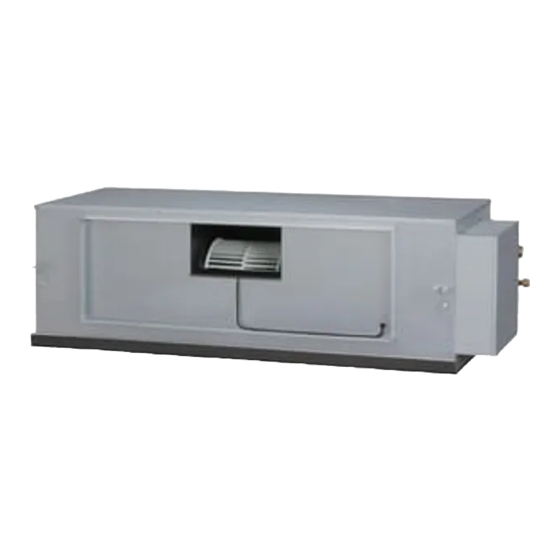
INDOOR UNIT (Outdoor air unit)
For authorized service personnel only.
MANUEL D'INSTALLATION
APPAREIL INTÉRIEUR (Unité d'air extérieur)
Pour le personnel agréé uniquement.
MANUAL DE INSTALACIÓN
UNIDAD INTERIOR (unidad de aire exterior)
Únicamente para personal de servicio autorizado.
PART NO. 9373870166-03
Advertisement
Table of Contents

Related Manuals for Fujitsu GENERAL AIRSTAGE AAUA48TLAV


Summary of Contents for Fujitsu GENERAL AIRSTAGE AAUA48TLAV
- Page 1 INSTALLATION MANUAL INDOOR UNIT (Outdoor air unit) For authorized service personnel only. MANUEL D’INSTALLATION APPAREIL INTÉRIEUR (Unité d’air extérieur) Pour le personnel agréé uniquement. AAUA48TLAV MANUAL DE INSTALACIÓN UNIDAD INTERIOR (unidad de aire exterior) Únicamente para personal de servicio autorizado. AAUA72TLAV PART NO.
-
Page 2: Table Of Contents
INSTALLATION MANUAL If Necessary, Get Help PART NO. 9373870166-03 These instructions are all you need for most installation sites and maintenance conditions. If you require help for a special problem, contact our sales/service outlet or your certifi ed VRF system indoor unit (Outdoor air unit) dealer for additional instructions. -
Page 3: About This Product
• Be sure to read this Manual thoroughly before installation. 2.3. Accessories • The warnings and precautions indicated in this Manual contain important information pertaining to your safety. Be sure to observe them. • Hand this Manual, together with the Operating Manual, to the customer. Request the WARNING customer to keep them on hand for future use, such as for relocating or repairing the unit. -
Page 4: Optional Parts
When installing, please refer to the installation manual of each optional part. 2.5. About unit of the length All Fujitsu General products are manufactured to metric units and tolerances. United Service States customary units are provided for reference only. -
Page 5: Pipe Installation
3.3.1. Conveyance method The side of the unit that holds the drain port A should be slightly lower than the opposite side of the unit B. The slant should allow from 0 to 13/16 in (0 to 20 mm) of difference •... -
Page 6: Selecting The Pipe Material
Dimension A [in (mm)] 4.1. Selecting the pipe material 0 (0) Pipe outside diameter Dimension B -0.015 (-0.4) Flare tool for R410A, [in (mm)] [in (mm)] clutch type CAUTION 1/4 (6.35) 3/8 (9.1) Do not use existing pipes from another refrigeration system or refrigerant. 3/8 (9.52) 1/2 (13.2) 0 to 0.020... -
Page 7: Pipe Connection [Brazing: For 72 Type]
Flare nut [in (mm)] Tightening torque [lbf·ft (N·m)] A p p l y n i t r o g e n g a s w h i l e Pressure regulating valve brazing the pipes. Nitrogen 1/4 (6.35) dia. 11.8 to 13.3 (16 to 18) gas pressure: 3/8 (9.52) dia. -
Page 8: Installing Drain Pipes
Hose opening view 5. INSTALLING DRAIN PIPES Wind the attached heat insulation • Use general hard polyvinyl chloride pipe ø 3/4 in [I.D.], ø 1-1/16 in [O.D.] and connect it around the hose band. Make sure the alignment is on top. with adhesive (polyvinyl chloride) so that there is no leakage. -
Page 9: Electrical Wiring
Refer to the table for the breaker specifi cations of each installation condition. Perform 6. ELECTRICAL WIRING the power crossover wiring within the range of the same refrigerant system. When the crossover wiring is done, make a connection for indoor units to satisfy conditions A and B WARNING below. -
Page 10: Unit Wiring
6.3.2. Transmission and Remote controller cable 6.3. Unit wiring Transmission cable Before attaching the cable to terminal block. 1 in (25 mm) 6.3.1. Power supply cable Adjust the length of power supply cable to avoid excessive tension with referring fi gure below. -
Page 11: External Input And External Output (Optional Parts)
6.5. External input and external output (Optional parts) CAUTION For 2-wire type For 3-wire type Do not operate any switches other than prescribed, as it can cause the unit to operate Y1:Non-polar Y1:Red improperly or malfunction. Connect the remote Y2:Non-polar Y2:White DIP switch controller cable... - Page 12 ● When function setting is “Operation/Stop” mode. DC power supply [In the case of “Edge” input] P.C.B 12 to 24V Connector Input signal Command Load resistance OFF → ON Operation CNA01 Ch1 of CNA01 or CNA02 ON → OFF Stop P.C.B Load [In the case of “Pulse”...
-
Page 13: Ir Receiver Unit (Optional Parts)
(2) External output • A twisted pair cable (22AWG) should be used. Maximum length of cable is 82 ft (25 m). • Use an external input and output cable with appropriate external dimension, depending on the number of cables to be installed. •... -
Page 14: Field Setting
Table A 7. FIELD SETTING Rotary Rotary Address Address There are 3 methods for address setting by FIELD SETTING as follows. Switch Setting Switch Setting Set by either of the methods. Each setting method is described (1) to (3) below. REF AD SW IU AD SW Refrigerant circuit... -
Page 15: Fan Delay Setting
Function 7.2. Fan delay setting Function Setting number Default Details number It is a function to delay the stop of cooling fan when the air conditioner is stopped. Allow an external controller to start ○ Start/Stop or stop the system, or to perform When auxiliary heater is connected, turn “ON”... -
Page 16: Check List
Error indications Wired Remote 9. CHECK LIST Controller Error contents OPERATION TIMER lamp FILTER lamp Error code lamp (green) (orange) (red) Pay special attention to the check items below when installing the indoor unit(s). After installation is complete, be sure to check the following check items again. Indoor unit main PCB error Check...
Need help?
Do you have a question about the GENERAL AIRSTAGE AAUA48TLAV and is the answer not in the manual?
Questions and answers