Sveaverken F100 Software User Manual
Auto steer system
Hide thumbs
Also See for F100:
- Hardware installation manual (30 pages) ,
- Software user manual (119 pages) ,
- Software user manual (101 pages)

Subscribe to Our Youtube Channel
Related Manuals for Sveaverken F100


Summary of Contents for Sveaverken F100
- Page 1 Sveaverken F100 Auto Steer System Software User Manual Model: F100 ©Sveaverken All rights reserved.
- Page 2 Safety Instructions Before using the Sveaverken F100 Auto Steer System, make sure that you have read and understood all the safety requirements. Safety Symbols After the control terminal is powered on, safety warnings are displayed on the home screen for 3 seconds, as shown in the figure below.
- Page 3 3. Make sure the antenna and angle sensor are installed properly. If there is any movement, please calibrate it again before using it. 4. Please do not use worn or damaged cables. Please purchase and replace new cables in time. Others 1.
-
Page 4: Table Of Contents
ContentsSafety Instructions ....................................I Contents ............................................ III Chapter I About This Document ..................................1 1 Purpose .......................................... 1 2 Technical Support ....................................... 1 Chapter II Product Overview ....................................2 1 Introduction ........................................2 2 Main Components ...................................... 2 3 Hardware Interfaces of Control Terminal ............................3 Chapter Ⅲ... - Page 5 7.3.2 Working Width Alerts ..............................46 7.3.3 Auxiliary Functions ................................46 7.3.4 Parameter Setting ................................48 7.3.5 Implement Information..............................50 7.3.6 Troubleshooting ................................52 7.3.7 Vehicle Parameters ................................53 7.3.8 System Settings ................................. 54 7.3.9 Wi-Fi Camera (Optional) ..............................56 7.3.10 Remote Commissioning ...............................
-
Page 6: Chapter I About This Document
Chapter I About This Document 1 Purpose This manual briefly describes how to use the Sveaverken F100 Auto Steer System for agricultural vehicles through simple and clear operation processes, so that users can learn to perform each operation easily, quickly, and accurately. -
Page 7: Chapter Ii Product Overview
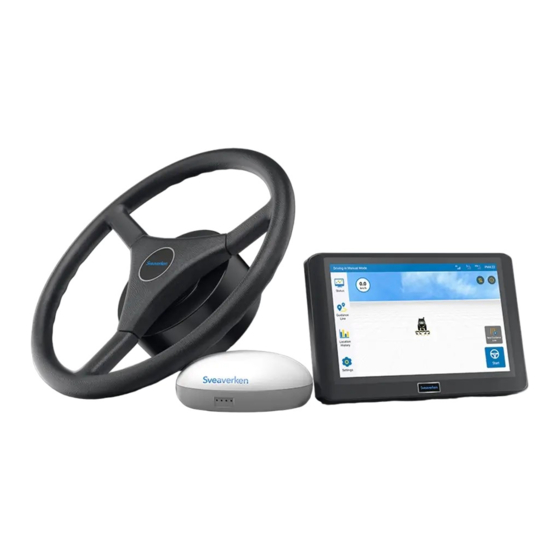
Chapter II Product Overview 1 Introduction For details, refer to Sveaverken F100 Auto Steer System on the Sveaverken official website: https://www.sveaverken.com Product standard: Q/440300 SVEA 001-2022. 2 Main Components Main components 1. Control Terminal: Provides human-machine interaction interfaces for vehicle control and communication. -
Page 8: Hardware Interfaces Of Control Terminal
Hardware Interfaces of Control Terminal Hardware interfaces of the control terminal... -
Page 9: Chapter Ⅲ Software Operation Instructions Of Control Terminal
2 Commissioning Use the following workflow to install and commission the Sveaverken F100 Auto Steer System for the first time: Select a language → Register and log in to your account → Enter installation information → Source Connection → Set vehicle parameters →... -
Page 10: Entering Installation Information
Therefore, please strictly follow the following procedure: Step 1:Enter user information, and tap Next step. Entering user information Step 2:Enter Sveaverken information, and tap Next step. Enter Sveaverken information Step 3:Enter all the required vehicle information, and tap Save to open the home screen. -
Page 11: Home Screen
Entering agricultural vehicle information Note: The system loads the control mode according to the vehicle type you selected, so select the vehicle type you actually use. 2.4 Home Screen After successfully logging in to the system, you will enter the home screen. You can view the network connection status and operation status in real time. -
Page 12: Main Interface Of Fast Mode
Mode Selection Fast mode The operation is simpler. The task can be started directly after importing the guidance line. Advanced mode Upgrade the field management function, start the operation after completing the task configuration, and have a more systematic management of the field data. Note: The guidance line used in the advanced mode cannot be adapted to the extreme Fast Mode. -
Page 13: Main Interface Of Advanced Mode
of operation status. (Note: Wi-Fi camera needs to be purchased separately.) 9. Perspective switch: Fix the perspective of three-dimensional view by tapping the button. 10. New Guidance line: Set new guidance line by tapping this shortcut button. 11. Autosteering start / Stop button: Tap to start or stop the vehicle. 12. -
Page 14: Select Correction Source
otherwise, it will enter the task configuration interface. 2.5 Select Correction Source You can connect to three correction sources: Mobile Base Station, Network RTK and SBAS. 1)Mobile Base Station: You need to select and power on a radio station, and pair with it. 2) Network RTK: You can set up an RTK connection through the network, when a CORS base station nearby and you have a local Ntrip account or FJ CORS account. - Page 15 Applicable to FJD base station with service code of BSXXXXXX and BSAXXXXXX. Enter the service code ② Pairing via frequency: After switching on base station, go to Settings – Correction Signal Sources, and choose mobile base station - Pairing via Frequency, and input the Frequency in the prompt. Click OK after confirming the information is correct.
- Page 16 Entering the frequency code Network RTK:To connect to the Network RTK, enable Network RTK and tap Connect. In the displayed ⚫ dialog box, enter your Ntrip domain name and account information. Ntrip domain: Enter the host and port, and tap Get Source. The source node field automatically shows the port having the strongest signal strength, indicating that the Ntrip domain information is completed.
-
Page 17: Setting Vehicle Parameters
Status becomes 2, and the source icon in the upper right corner changes to SXX. XX is the age of differential, which is a number from 0 to 20. Note: 1. It takes up to 3 minutes to connect to a mobile base station or network RTK, and up to 5 minutes to connect to SBAS. 2. -
Page 18: Calibrating Angle Sensor
Setting List Vehicle information *For details about the measurement operations, please check the corresponding commissioning instruction video. 2.7 Calibrating Angle Sensor After completing vehicle parameter settings, you need to calibrate the angle sensor. Perform the following operations to calibrate the angle sensor: Step 1: Choose Settings ->... - Page 19 Select angle sensor type If the selected type is "Hall Sensor", then the user needs to select the installation position of the angle ⚫ sensor. After selecting the installation location, click "Calibrate" to directly enter the calibration process. Please follow the prompts in the following interface to calibrate.
- Page 20 Turning the wheel to the center If the angle sensor type is selected as "attitude sensor", please then select the installation position of your angle ⚫ sensor. Note: when you choose “attitude sensor”, you should drive straight for 15-20m in manual mode to complete data convergence every time you open the system.
-
Page 21: Vehicle Calibration
Detecting the speed ratio Detect finished If the sensor type is switched, the device needs to be restarted after the sensor is switched to take effect. 2.8 Vehicle Calibration After angle sensor calibration finished, you need to calibrate vehicle to correct working offset. On the displayed Settings screen, tap into “Vehicle Calibration”... - Page 22 Vehicle Calibration Start Calibration Step 1: Move the agricultural vehicle to the starting point and tap Confirm Point A on the screen. Confirm Point A Step 2: After confirming Point A, manually drive the vehicle straight for 50m and Confirm Point B. During the driving towards Point B, the distance traveled will be displayed on the upper right corner of the screen in real time.
- Page 23 Confirm Point B Step 3: After confirming Point B, please follow the prompt 2. on the screen to manually turn the vehicle around and make it return to Point B on the guidance line just confirmed (with the front end of the vehicle facing Point A). After the adjustment is completed, tap Start to make the vehicle run to Point A in the autosteering driving mode according to the guidance line just confirmed.
-
Page 24: Preparatory Operations
Manually turning around and start the auto-working Step 6: After the vehicle reaches Point B in the autosteering driving mode, tap Stop to stop the current autosteering driving operation. Stop autosteering driving after reaching the point A Step 7: tap Calibrating completed to complete the vehicle calibration and return to the home screen. Calibration finished After completing the above steps of commissioning, you can start to use control terminal for intelligent operations. -
Page 25: Getting The Course Angle
Confirm the source connection mode (2) Check whether the connection is normal. If the Network RTK mode is used, "RTK" is displayed in the upper right corner. Then, check whether you have full signal bars in the status bar. "RTK" displayed in the upper right corner when the RTK mode is used 3.2 Getting the Course Angle If the RTK connection is normal, drive ahead and accelerate the vehicle for more than 5s(Only one operation is required for each startup). -
Page 26: Import Guidance Line
setting points A and B to save a new guidance line, and import the new guidance line to the current operation. For more specific instructions on creating guidance lines, please refer to Chapter 4 to create a guidance line. 3.3.2 Import Guidance Line You can directly import the required guidance line from the list of guidance lines to the current operation as follows: Step 1: If you have already saved the guidance line before, please find out the line you want to import in the list of guidance lines. -
Page 27: Add And Select Fields
Preparatory operation flow chart 3.4.1 Add and Select Fields Click "Task" button on the left to enter the task configuration interface. First, add and select an operation field. Task configuration entry The configuration field interface is shown in the figure below: Configure field interface 1. -
Page 28: Add And Select Task
Note: If the field is not selected, it is impossible to set the boundary, guidance line and task setting. Add field After filling in the corresponding field name, farm owner and farm name, click “Save”. Interface for adding field 3.4.2 Add and Select Task Click Task Name to add or select from the list the intended task. - Page 29 Interface for configuring boundary 1. Boundary list: Display the existing boundary, including name of boundary, the operatable area enclosed and the creation time. 2. Change the distance to the edge of the field: Modify the margin of the boundary offset inward or outward, is zoomed in or out, remind users of the position of the edge of the field or the place where to turn around.
- Page 30 Interface of boundary plan When finished, press the "Pause" button and choose "Save". Interface when finished recording the boundary When saving, you need to fill in the boundary name, margin and the offset. During operation, a pop-up window will prompt when the distance from the field edge is 30m. Interface of saving the boundary When saving the boundary, if the boundary does not meet certain requirements, the following adjustments will be given for different situations:...
-
Page 31: Add And Select Guidance Line
Adjustments for irregular boundaries Boundary situation Adjustments Example Auto-completion of x<10m boundary Distance Connect with a 10m<x<50m between straight line two ends 50m<x Continue recording Length of boundary < 80m Crossed boundary Auto-optimization Special Boundary too boundary narrow Boundary Re-recording contains multiple sub-area 3.4.4 Add and Select Guidance Line... -
Page 32: Confirm Task Configuration
on creating guidance lines, please refer to Chapter 4 to create a guidance line. 3.4.5 Confirm Task Configuration After all the information are selected, click confirm button, and an information confirmation window will pop up. After confirming that the configuration information is correct, click“OK”. Click "Start" button on the homepage to enter the operation interface. - Page 33 Adding guidance lines in Advanced Mode Detailed steps for creating different guidance lines are shown below. Straight Line Mode ⚫ Step 1: Move the vehicle to the starting point of the operation, and tap Confirm Point A on the screen of control terminal to determine the current position as Point A of the new guidance line.
- Page 34 top of the list. Import Guidance Line Curve Mode ⚫ Step 1: On the displayed Guidance Line setting page, tap Straight Line to switch the plotting mode to the curve. After switching to the curve mode, please move the vehicle to the starting point of the operation, and tap Confirm Point A on the screen to confirm the current position as Point A on the curvilinear guidance line.
- Page 35 Import new guidance line Notes for the curve mode: 1. In the curvilinear mode, Point A is the starting point and Point B shall be a point on another field edge. 2. In multi-line mode, make sure to travel in the same line lengths as the curvilinear guidance line, or the route beyond the curvilinear guidance line will gradually tend to be a straight line.
- Page 36 Switch to Pivot Mode Step 2: Set point A at the starting point, drive the vehicle along the outer edge of the circular field for at least 20m, set point B and click "Save". Set point A Set point B Step 4: Enter the distance from the edge of the implement to the edge of the field, click "Confirm", enter the name of the guidance line and then save.
- Page 37 Set field edge distance Interface of working with Pivot Mode Note: When working with Pivot Mode, when the vehicle is 20m away from the starting point, please follow the instructions in the notification to get prepared to disengage from auto mode and enter the next work path, and then repeat the above operations until all paths are completed.
-
Page 38: Start Operation
5 Start Operation 5.1 Operation Interface ⚫The interface of Fast Mode Operation interface 1. Operation record button: Yellow means that the current operation data is recording. And white means that the current operation data is not recorded. Click to switch the recording status. 2. -
Page 39: Operation Setting
2. Task record: If it is in blue it indicates that the current task data is being recorded, and if in white it indicates that the current job data is not recorded. Click to switch it on and off. 3. Auto mode: If it is in blue it means it is in auto-steering state, and if in white means it is not in auto-steering state. Click to switch between two driving modes. - Page 40 marking the boundary. Autopilot status: Navigation automatically controls the steering wheel to assist straight line operations. The operation of marking the field can be carried out during automatic driving, and other operation setting operations should be switched to manual mode. (3) Guidance Line Translation In the manual mode after starting the task, the user adjusts the guidance line in the current multi-line mode to the left and right according to the needs of the actual operation, and drives according to the adjusted guidance line.
- Page 41 Translate to the fixed position Note for The Use of Shifting Guidance Line: Shift guidance line function is available only in the manual driving status in the multi-line mode. (4) Switch operation mode The operation mode is divided into single-line mode and multi-line mode. The user can click "multi-line mode/single- line mode"...
- Page 42 (5) Mark the Edge Marking the field edge After importing guidance line or during the intelligent operation, you can enable the function of marking the field edge according to the actual needs. This function can alert the user when the vehicle is about to reach the field edge of another side, thereby effectively avoiding safety accidents especially in dark environment.
-
Page 43: Advanced Functions
Red dashed line that guides the tractor 6 Advanced Functions Users can use the advanced functions in the advanced mode after the advanced mode is activated. The existing advanced function is Uturn. which can be selected and used according to the actual situation. Setting list Advanced functions ⚫Uturn: Automatically plans paths at any position in the field for automatic Uturns and headland operations. - Page 44 Rectangle or approximate rectangle fields 2. Quadrilateral fields with large included angles Quadrilateral fields with large included angles 3. Approximate quadrilateral fields with small missing parts Approximate quadrilateral fields with small missing parts Shapes of fields that can be partially planned: 1. Quadrilaterals with large missing parts 2. Polygons, triangles, teardrops, and other shapes with large triangular space Shapes of fields that can be partially planned Fields that cannot be planned: 1.
- Page 45 Set the turning radius Set the implement parameters 2.Choose Settings > Advanced functions > Uturn, and enable or disable the function. Uturn details 3.Tap Task and choose the field, boundary, and guidance line. If you select No guideline, the guidance line will be generated automatically when the Uturn function is enabled.
- Page 46 Choose the boundary and the guidance line when creating an operation 4.Tap Start, drive the vehicle to the Uturn start point, and tap the Uturn icon on the right. Operation screen Note: If No guideline is selected, the pop-up dialog "There is no guidance line, whether to generate it automatically?" appears.
- Page 47 Setting interface of Uturn system If you choose to perform the headland operation, the vehicle performs it based on the boundary shape. ⚫ Automatic headland operation when you choose to perform it If you choose not to perform the headland operation, the system recommends the optimal headland path when ⚫...
- Page 48 Uturn coverage 7.Follow the green line to drive to the start point, and tap Start. Start the Uturn task Note: ⚫Before confirming the Uturn settings, ensure that your vehicle is close to the start point, and heading to the working direction of a guidance line.
-
Page 49: Other Functions
7 Other Functions 7.1 Status Status Users click the "Status" to access the working status and operation of the vehicle. Offset distance: Offset distance of the vehicle; Real-time speed: Real-time speed of the vehicle; Current heading: Current heading angle of the vehicle; Guidance line heading: The heading angle of the AB line;... -
Page 50: Settings
to refresh the list. 3. Filter the operation list. In the Fast Mode, users can filter the operation data by the operation time; in the Advanced Mode, users can filter the historical operation information by date, field and operation type. After the filter data is filled in, click "Filter"... -
Page 51: Working Width Alerts
3. After connection, check the signal icon in the top status bar. If the RTK mode is used, "RTK" is displayed; If the icon does not change after a few minutes, reconnect or switch the connection mode. For details, see section 2.5 "Source Connection". - Page 52 Map information, including field, boundary, guidance line, and task data, can be exported out of or into the autosteering through online sharing or USB flash drive. Sveaverken Online Sharing: Before the USB flash drive is inserted, data can be transferred to the designated user through online sharing. The steps are as follows: Step 1: Go to Settings >...
-
Page 53: Parameter Setting
Select the device SN Notes: 1.Only data in the formats specified on the screen can be imported. 2.Task data cannot be shared online. 7.3.4 Parameter Setting Choose Settings -> Parameter Settings. On the displayed screen, you can set Angle Sensor, Vehicle Calibration and Calibration of Accessories to ensure operational accuracy. - Page 54 ⚫ Calibration of Accessories Settings for calibration of accessories When auto-driving path has an offset within 3 cm after the implement is equipped, please measure the value. If the auto-driving path tends to the left comparing to the pre-set guidance line, please select "implement offset to the left" and enter the deviation value “a”, and then click "OK"...
-
Page 55: Implement Information
Vehicle Calibration Vehicle calibration For detailed operations, see section 2.8 Vehicle Calibration in Chapter IV Software Operation Instructions of In-vehicle Control Terminal. 7.3.5 Implement Information Tap Implement Information in Settings to view the implement parameters and list of implements. Tap Implement Parameters to view the way of implement connection, the distance between the implement and the hitch, and implement working parameters. - Page 56 ⚫ Delete the Implement: Select an implement and tap Delete to delete the implement information. Delete an implement ⚫ Edit the Implement: Select an implement and tap Edit to modify the implement information. Edit an implement ⚫ Create New Implements: Tap New and then perform the following steps: Step 1: Fill in the basic information of the new implement and tap Next.
-
Page 57: Troubleshooting
Create new implements - work information ⚫ Upload the Implement: Tap the upload icon to upload implement information. Upload implements ⚫ Synchronize the Implement: Tap the synchronize icon to synchronize the previously uploaded implement information. Synchronize implement 7.3.6 Troubleshooting If encountering any problem during use, the user can enter “Troubleshooting” to perform software and hardware detection of the vehicle. -
Page 58: Vehicle Parameters
Troubleshooting 7.3.7 Vehicle Parameters Vehicle parameter settings Tap the “Vehicle Parameters” tab. On the displayed details screen, tap the required items and enter the corresponding vehicle data to complete vehicle parameter settings. For specific measurement details, please refer to the instruction video. Positioning antenna spacing calibration If there is a problem of large and small lines in the multi-line mode during the operation, the user is required to calibrate the positioning antenna spacing according to the following diagram. -
Page 59: System Settings
First driving: Drive the vehicle at a low speed from point A to point B. If the vehicle is stable (the offset error displayed on the screen is less than 2 cm), stop after the driving distance is not less than 10 meters, and mark at the right rear tire position of vehicle, confirm the marking line L1. - Page 60 Note: Do not change the file name of the upgrade package. Notes for upgrade: 1. Ensure that the network status is stable throughout the OTA upgrade process. 2. Do not power off the terminal during the upgrade process. 3. If you encounter any problems during the upgrade, please contact your local dealer for help or call the technical service hotline.
-
Page 61: Wi-Fi Camera (Optional)
⚫ Language Settings You can select a system language from several languages, such as Chinese, English, Spanish, and Russian. Note: Language switching is not supported during operation. Language selection 7.3.9 Wi-Fi Camera (Optional) Two Wi-Fi cameras can be connected via hotspot. The operation is as follows: 1. -
Page 62: Remote Commissioning
Real-time video 7.3.10 Remote Commissioning Turn on the remote commissioning function, which should use with the background control program to realize the remote control screen function; user should turn on the remote commissioning switch in the settings. Remote commissioning 7.3.11 Changing the Password In Settings >... -
Page 63: Other Settings
Login 7.3.12 Other Settings In addition to Parameter Settings, Correction Source, and Troubleshooting, the Settings screen allows setting and querying other general information such as Volume, Brightness, and device information. -
Page 64: Chapter Ⅳ Faqs
Chapter Ⅳ FAQs Fault Troubleshooting Check whether the rolling angle and pitching angle change in real time. S turn in autosteering operations Calibrate the angle sensor (optional). Check whether the GNSS receiver is installed and connected properly. Check the brake. Test the motor. -
Page 65: Chapter Ⅴ Nameplate Position
Chapter Ⅴ Nameplate Position Note: The nameplate is fixed on the side of the motor by rivets, and the motor is fixed under the steering wheel. -
Page 66: Appendix
Appendix 1 Specification Table 1 Assembly Component Specifications Size: 275×180×40 mm; Basic configuration: 10.1-inch capacitive touch screen, LED backlight, 1280x800 pixels, LCD>500 nits RAM: 2G; ROM: 8G Signals: RF signal, positioning satellite signal, and 4G signal; External interface: SIM card slot*1, Type-C port*2; Control Terminal Control Terminal Power supply: 9 V - 36 V;... -
Page 67: Specification Table 2
Types of onboard computer interfaces UART, IIC, SPI, GPIO, USB, and Ethernet Onboard computer data input and output Sveaverken proprietary communication protocol V1.0 protocol Dual-frequency receiver; BDS B1/B2, GPS L1/L2, Type and frequency range of GNSS receiver GLONASS L1/L2, GALILEO E1/E5b, and SBAS Firmware version of GNSS receiver V1.1... - Page 68 ©Sveaverken All rights reserved.
Need help?
Do you have a question about the F100 and is the answer not in the manual?
Questions and answers