Sveaverken F100 Hardware Installation Manual
Auto steer system
Hide thumbs
Also See for F100:
- Software user manual (68 pages) ,
- Software user manual (119 pages) ,
- Software user manual (101 pages)

Related Manuals for Sveaverken F100


Summary of Contents for Sveaverken F100
- Page 1 Sveaverken F100 Auto Steer System Hardware Installation Manual © Sveaverken All rights reserved.
- Page 2 Sveaverken F100 Auto Steer System Hardware Installation Manual Copyright Notice: Sveaverken reserves the copyright for this manual and all contents herein. No part of this manual may be reproduced, extracted, reused, and/or reprinted in any form or by any means without the prior written permission of Sveaverken.
- Page 3 Sveaverken F100 Auto Steer System Hardware Installation Manual Disclaimer The purchased products, services, and features are stipulated by the contract. All or part of the products, services, and features described in this manual may not be within the scope of your purchase or usage. Unless otherwise specified in the contract, all the content in this manual is provided "AS IS"...
- Page 4 Sveaverken F100 Auto Steer System Hardware Installation Manual Preface Thank you for purchasing Sveaverken’s product. This manual provides detailed hardware installation guide. If you have any questions, contact the local dealer. Purpose and Intended Users This manual introduces the physical characteristics, installation procedures, and technical specifications of the product as well as the specifications and use of the wiring harnesses and connectors.
-
Page 5: Table Of Contents
Sveaverken F100 Auto Steer System Hardware Installation Manual Contents 1 Product Introduction ..........................1 2 Preparation Before Installation ...................... 2 2.1 Safety Instructions ......................... 2 2.1.1 Installation ........................2 2.1.2 Disassembly ........................2 2.1.3 Electrical Operations ....................2 2.2 Installation Requirements.....................2 2.2.1 Installation Position .................... - Page 6 Sveaverken F100 Auto Steer System Hardware Installation Manual 5.1 Site Requirements ........................21 5.2 Power-on ............................. 21 5.2.1 Inspection Before Power-on ..................21 5.2.2 Inspection After Power-on ..................21 5.3 Parameter Calibration ......................21 6 Appendix ..............................22 6.1 Specifications ......................... 22 - VI - ©...
-
Page 7: Product Introduction
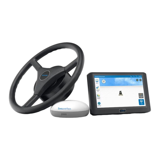
Sveaverken F100 Auto Steer System Hardware Installation Manual 1 Product Introduction Sveaverken F100 Auto Steer System is an autosteering system that is launched by Sveaverken for agricultural machinery and supports assisted straight line driving. The system consists of the control terminal, GNSS receiver, electric steering wheel, and wiring harnesses. -
Page 8: Preparation Before Installation
Sveaverken F100 Auto Steer System Hardware Installation Manual 2 Preparation Before Installation 2.1 Safety Instructions Before installation, read the safety advice in this manual carefully to avoid doing harm to people and equipment. Note that the following safety advice cannot cover all possible dangerous situations. -
Page 9: Air
Sveaverken F100 Auto Steer System Hardware Installation Manual Avoid high temperature and humidity. In summer, protect the control terminal from direct sunlight, and note that appropriate space must be maintained between the shelter and the control terminal. The equipment will be damaged if it works under improper environmental temperature and humidity. -
Page 10: Unpacking And Inspection
Sveaverken F100 Auto Steer System Hardware Installation Manual Installation Tools for Sveaverken F100 Auto Steer System Tool Specifications Qty. Function machine model) and motor bracket. Disassemble and install the front axle shaft cover bolts 18/21 (bolt size depends on the machine model). - Page 11 Sveaverken F100 Auto Steer System Hardware Installation Manual Assembly Component Qty. Remarks Antenna bracket assembly Ⅱ 3M sticker Prevailing torque type hexagon nuts with flange style Fix the GNSS Small self- receiver and sealing bag 1 Hexagon bolt 5/8- antenna bracket assemblies.
-
Page 12: Inspection
Sveaverken F100 Auto Steer System Hardware Installation Manual 3 Inspection Read Chapter 2 carefully, and ensure all requirements specified in this chapter are met before installation. 3.1 Inspection Before Installation Before installation, make a detailed plan and arrangement regarding the installation position, power supply, and wiring of the equipment, and ensure that: ... -
Page 13: Installation
Sveaverken F100 Auto Steer System Hardware Installation Manual 4 Installation 4.1 Installing the Electric Steering Wheel 4.1.1Components Electric Steering Wheel Assembly Name Qty. Remarks Dust cap Hexagon socket head cap screw M4×14 Spring washer M4 Plain washer M4 Packed in the... -
Page 14: Installation Steps
Sveaverken F100 Auto Steer System Hardware Installation Manual Electric Steering Wheel Assembly Name Qty. Remarks and shown below. Plain washer M6 Spring washer M6 Hexagon socket head cap screw M6×16 *An example of 2# motor bracket is shown below. 2# Motor Bracket (Component 7 of the Electric Steering Wheel Assembly) Name Qty. - Page 15 Sveaverken F100 Auto Steer System Hardware Installation Manual 2. Install the splined sleeve on the steering column , and check whether the splined sleeve is appropriate by rotating it to see whether there are any sways or gaps. As the steering column on the machine varies, you may try several splined sleeves to select the one that fits.
- Page 16 Sveaverken F100 Auto Steer System Hardware Installation Manual 4. Fix the steering motor and motor bracket with two M6 16 hexagon socket head × cap screws , two M6 spring washers , and two M6 plain washers . Do not fully torque the screws at this time.
- Page 17 Sveaverken F100 Auto Steer System Hardware Installation Manual 6. Install the lock nut removed in step 1 on the splined sleeve and install the dust cap . - 11 - © Sveaverken All rights reserved.
-
Page 18: Installing The Gnss Receiver
Sveaverken F100 Auto Steer System Hardware Installation Manual 4.2 Installing the GNSS Receiver 4.2.1Components Name Qty. Remarks GNSS receiver 3M sticker Prevailing torque type hexagon nuts with flange style 2 Antenna bracket assembly Plain washer M16 Spring washer M16 Hexagon bolt 5/8-11 Self drilling screw Antenna bracket assembly Ⅱ... - Page 19 Sveaverken F100 Auto Steer System Hardware Installation Manual 2. Connect the GNSS receiver and the antenna bracket assembly to the antenna bracket with four prevailing torque type hexagon nuts with flange style 2 . assembly Ⅱ 3. Install the GNSS receiver and the antenna bracket assemblies at the top of the machine where it is firm and has low vibration with four self drilling screws.
-
Page 20: Installing The Angle Sensor
Sveaverken F100 Auto Steer System Hardware Installation Manual 4.3 Installing the Angle Sensor 4.3.1Components Remarks Name Qty. Assembly bolt M3×8 Angle sensor Angle sensor bracket 4.3.2Installation Steps 1. Remove the front axle shaft cover bolts . 2. Install the angle sensor on the front axle, adjust the wiring harness, and install and tighten the bolt removed in step 1. -
Page 21: Installing The Radio Antenna
Sveaverken F100 Auto Steer System Hardware Installation Manual 4.4 Installing the Radio Antenna 4.4.1Components Remarks Name Qty. Radio antenna Sucker base 3M sticker 4.4.2Installation Steps If there is no suitable metal plane on top of the machine, select and clean a suitable plane to install the antenna. -
Page 22: Installing The Control Terminal
Sveaverken F100 Auto Steer System Hardware Installation Manual If there is a suitable metal plane on top of the machine, wipe the plane clean, and then directly suck the radio antenna to the plane. 4.5 Installing the Control Terminal 4.5.1Components... -
Page 23: Installing The Sim Card
Sveaverken F100 Auto Steer System Hardware Installation Manual 2. Turn anticlockwise the hand screw to loosen it, and place the ball joint of the control terminal into the socket of the control terminal bracket. 3. Place the socket of the control terminal bracket on the ball joint of the control terminal mounting base in the same way as in step 2, and turn the hand screw ... -
Page 24: Installation Steps
Sveaverken F100 Auto Steer System Hardware Installation Manual communication module of the control terminal. Ensure that the SIM card supports the following 4G frequency bands: LTE-FDD: B1/B2/B3/B4/B5/B7/B8/B12/B13/B18/B19/B20/B25/B26/B28 LTE-TDD: B38/B39/B40/B41 UMTS: B1/B2/B4/B5/B6/B8/B19 GSM: B2/B3/B5/B8 Ensure that you have data service with your SIM card. -
Page 25: Installation Steps
Sveaverken F100 Auto Steer System Hardware Installation Manual Spare main wiring harness GNSS receiver wiring harness Main power cable Angle sensor assembly Radio antenna 4.7.2Installation Steps Install the wiring harnesses according to the figure below. Notes: 1. Do not plug or unplug the harness connectors or connect equipment when the power is on. - Page 26 Sveaverken F100 Auto Steer System Hardware Installation Manual Installation Tips: 1. Main/Spare wiring harness: Lock the door on the right side of the cab, and then sort out the wiring harness and fix it on the right door handle or the A-pillar at the right front of the cab with nylon cable ties.
-
Page 27: System Commissioning
1. Check whether the power indicator of the control terminal is lit. 2. Turn on the control terminal, and check whether the system program starts normally. Parameter Calibration For details, refer to the Sveaverken F100 Auto Steer System Software User Manual . - 21 - © Sveaverken All rights reserved. - Page 28 Sveaverken F100 Auto Steer System Hardware Installation Manual 6 Appendix 6.1 Specifications Component Specifications Size: 275×180×40 mm Basic configuration: 10.1-inch capacitive touch screen, LED backlight, 1280×800 pixels, > 500 nit LCD, speaker, 2G RAM, 8G ROM External interface: SIM card slot×1, Type-C port×2 Power supply: 9 V –...
- Page 29 Sveaverken F100 Auto Steer System Hardware Installation Manual Component Specifications Splined sleeve Multiple sizes Frequency range: 410 MHz - 470 MHz Voltage standing wave ratio: ≤2.0 Gain: 1±0.5 dBi Radio antenna Impedance: 50 Ω Polarization: vertical Size: ø82 mm×490 mm Operating temperature: -20°C to 60°C...
- Page 30 © Sveaverken All rights reserved.
Need help?
Do you have a question about the F100 and is the answer not in the manual?
Questions and answers