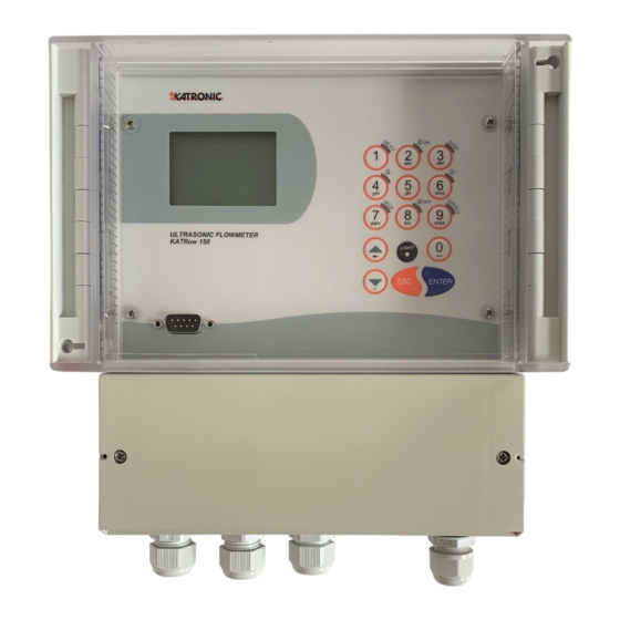
Katronic KaTflow 150 Operating Instructions Manual
Ultrasonic flowmeter
Hide thumbs
Also See for KaTflow 150:
- Operating instructions manual (67 pages) ,
- Quick start manual (3 pages) ,
- Quick start manual (3 pages)

Related Manuals for Katronic KaTflow 150


Summary of Contents for Katronic KaTflow 150
- Page 1 All manuals and user guides at all-guides.com Operating Instructions Ultrasonic Flowmeter KATflow 150...
- Page 2 All manuals and user guides at all-guides.com Katronic Technologies Ltd. 23 Cross Street Leamington Spa Warwickshire CV32 4PX United Kingdom Tel. +44 (0)1926 882954 Fax +44 (0)1926 338649 Internet www.katronic.co.uk E-mail mail@katronic.co.uk Operating Instructions KATflow 150 Version V11E0310 Copyright © 2010 All rights reserved.
-
Page 3: Table Of Contents
All manuals and user guides at all-guides.com KATflow 150 Table of Contents KATflow 150 Operating Instructions Table of Contents Page 1 Safety instructions, legal requirements, warranty, return policy....5 1.1 Symbols used in these operating instructions..........5 1.2 Safety instructions..................5 1.3 Warranty......................6 1.4 Return policy....................6... - Page 4 All manuals and user guides at all-guides.com KATflow 150 Table of Contents 5.4.3 Analogue current output 0/4 ... 20 mA...........32 5.4.4 Digital Open-Collector output..............32 5.4.5 Digital relay output.................32 5.5 Input configurations..................33 5.5.1 PT100 inputs..................33 5.5.2 Analogue current input 0/4 ... 20 mA............33 5.6 Heat quantity measurement (HQM)..............33...
-
Page 5: Safety Instructions, Legal Requirements, Warranty, Return Policy
● Install the equipment and cabling securely and safely according to the rel- evant regulations. ● If the product does not operate normally, please refer to the service and troubleshooting instructions, or contact KATRONIC for help. -
Page 6: Warranty
1.4 Return policy If the flowmeter has been diagnosed to be faulty, it can be returned to KATRONIC for repair using the Customer Returns Note (CRN) attached to the Appendix of this manual. KATRONIC regret that for Health & Safety reasons we cannot accept the return of the equipment unless accompanied by the completed CRN. -
Page 7: Introduction
2 Introduction 2 Introduction Clamp-on transit- The KATflow 150 is an ultrasonic flowmeter employing clamp-on sensors for the measurement of liquids in full, enclosed pipes. Flow measurements can be under- time flowmeter taken without interruption of the process or interference with the integrity of the pipeline. -
Page 8: Installation
3.1.3 Identification of components The following items are typically supplied (please refer to your delivery note for a detailed description): ● KATflow 150 ultrasonic flowmeter Clamp-on sensors (one pair for single channel operation, two pairs for dual ● channel operation) ●... -
Page 9: Clamp-On Sensor Installation
All manuals and user guides at all-guides.com KATflow 150 3 Installation 3.2 Clamp-on sensor installation The correct selection of the sensor location is crucial for achieving reliable meas- urements and high accuracy. Measurement must take place on a pipe in which sound can propagate (see Acoustic propagation) and in which a rotationally sym- metrical flow profile is fully developed (see Straight pipe lengths). - Page 10 All manuals and user guides at all-guides.com KATflow 150 3 Installation For a free inlet or outlet pipe section: Select the measuring point at a location where the pipe cannot run empty. Correct Disadvantageous Correct Disadvantageous For a vertical pipe: Select the measuring point at a location where the liquid flows upward to ensure that the pipe is completely filled.
- Page 11 All manuals and user guides at all-guides.com KATflow 150 3 Installation Disturbance source: 2 x 90° -elbows in different planes Inlet Outlet L ≥ 40 D L ≥ 5 D Disturbance source: T-section Inlet Outlet L ≥ 50 D L ≥ 10 D...
-
Page 12: Pipe Preparation
All manuals and user guides at all-guides.com KATflow 150 3 Installation 3.4 Pipe preparation Clean dirt and dust from around the area of the pipework where the ● sensors are to be placed. ● Remove loose paint and rust with a wire brush or file. -
Page 13: Flowmeter Installation
All manuals and user guides at all-guides.com KATflow 150 3 Installation 3.6 Flowmeter installation 3.6.1 Wall mounting The KATflow 150 is a wall mounted device and can be installed using suitable screws and wall plugs according to the following drawings. Flowmeter outline di- mensions 146.5 258.5... - Page 14 All manuals and user guides at all-guides.com KATflow 150 3 Installation Drilling aid for wall mounting 243.5 Drawing 2: Drilling aid for wall mounting Make sure that the ambient temperature is within the -10 ... 60 ° C operating tem-...
-
Page 15: Electrical Connections
Please note that in order to supply the unit with MAINS POWER, the equipment Electrical wiring must be protected by suitably sized switches and circuit breakers. 100 ... 240 V AC, 50/60 Hz 10 W 9 ... 36 V DC 10 W Drawing 3: Electrical connection diagram for the KATflow 150 flowmeter... -
Page 16: Clamp-On Sensor Mounting
All manuals and user guides at all-guides.com KATflow 150 3 Installation 3.7 Clamp-on sensor mounting Before the sensors can be mounted Sensor mounting ● the installation location should have been determined, ● a sensor mounting method should be chosen, the flowmeter must be mechanically and electrically installed, ●... -
Page 17: Correct Positioning Of The Sensors
All manuals and user guides at all-guides.com KATflow 150 3 Installation 3.7.3 Correct positioning of the sensors Correct sensor position Illustration 6: Correct positioning of the sensors Always mount the transducer pair so that the free front edges of the sensors face each other. - Page 18 All manuals and user guides at all-guides.com KATflow 150 3 Installation Pull the tension strap and guide the free end through the clamp so that the ● clamp hooks engage. Slightly tighten the screw on the clamp. ● Mount the second sensor in the same way.
-
Page 19: Operation
All manuals and user guides at all-guides.com KATflow 150 4 Operation 4 Operation 4.1 Switching On/Off The flowmeter is switched on by connecting the power supply to the instrument. Switching On/Off Disconnecting the external supply switches off the flowmeter. 4.2 Keypad and display... - Page 20 All manuals and user guides at all-guides.com KATflow 150 4 Operation Character entry: = Show negative total value < Character entry: > Character entry: = Show positive total value Character entry: Toggle MUltipleXer (where multi- channel functions are provided) Character entry:...
-
Page 21: Display Functions
All manuals and user guides at all-guides.com KATflow 150 4 Operation Confirm entry with saving ENTER menu item 4.2.2 Display functions Main measurement Display icons Menu header display Display line 1 Display line 2 Date, time (optional) Illustration 10: Main display functions... -
Page 22: Quick Setup Wizard
All manuals and user guides at all-guides.com KATflow 150 4 Operation Not used Time/date set Clock error Error recorded in error log No error detected Serial communication on (RS232 and/or RS485) Serial communication off Table 4: Display icons 4.3 Quick setup wizard... - Page 23 All manuals and user guides at all-guides.com KATflow 150 4 Operation Enter outside pipe diameter using alphanumer- ical keys and confirm by pressing <ENTER>. Use key <UP> as character backspace clear to correct for data entry errors. If 0 is entered, an additional screen appears that allows entering the pipe circumference.
-
Page 24: Measurements
All manuals and user guides at all-guides.com KATflow 150 4 Operation Use cursor keys to select Start Measurement. Confirm by pressing <ENTER>. Sensor placement screen: Mount transducers with suggested spacing and use middle bar for fine adjustment of position (central position is desired). -
Page 25: 3-Line Display Format
All manuals and user guides at all-guides.com KATflow 150 4 Operation 3-line display format Display screen Operation The three-line display screen is configure- able to show flow, totalizers and diagnostic functions. Change to diagnostic displays by pressing <DISP> and to totalizer screens by press- ing <NEXT>. -
Page 26: Commissioning
All manuals and user guides at all-guides.com KATflow 150 5 Commissioning 5 Commissioning 5.1 Menu structure Menu structure Main menu Menu level 1 Menu level 2 Description/settings Quick Start Setup Wizard Single Sensor type Indication of sensor type and serial number if automatically detected, otherwise select from list ↑↓... - Page 27 All manuals and user guides at all-guides.com KATflow 150 5 Commissioning Liner thickness Only if lining material selected 1.0 ... 99.0 mm Select from list ↑↓ Passes Auto 1...16 Setup Wizard Dual As setup wizard single for channel 1 Start...
- Page 28 All manuals and user guides at all-guides.com KATflow 150 5 Commissioning Passes Select from list ↑↓ Passes Output Select channel Channel 1, Channel 2 Display Select from unit list ↑↓ Units Damping Reduces fluctuations in the display output 1 ... 255 s...
- Page 29 All manuals and user guides at all-guides.com KATflow 150 5 Commissioning PT100 – Value read from PT100 temperature sensor in ºC Value Enter fixed user defined value 0 ... 250 ºC Offset Enter fixed user defined value -100 ... 100 ºC...
- Page 30 All manuals and user guides at all-guides.com KATflow 150 5 Commissioning Settings Date Example: 03/10/07 Time Example: 09:27:00 Select from list ↑↓ Date Format dd/mm/yy mm/dd/yy yy/mm/dd Select from list ↑↓ Language English German French Spanish Russian Keypad Enable keypad sound...
-
Page 31: Diagnostics
All manuals and user guides at all-guides.com KATflow 150 5 Commissioning 5.2 Diagnostics Diagnostic screens can be viewed directly during measurement or through the menu structure. 5.3 Display settings The main Process Value (PV) is the primary measurement data. Customer specific settings for data to be displayed can be achieved by accessing the appropriate menu items. -
Page 32: Analogue Current Output 0/4
All manuals and user guides at all-guides.com KATflow 150 5 Commissioning 5.4.3 Analogue current output 0/4 ... 20 mA Analogue outputs The analogue current outputs operate in a 4 ... 20 mA or 0 ... 20 mA span. Current outputs may be assigned to process values in the “mode” section of the output menu. -
Page 33: Input Configurations
All manuals and user guides at all-guides.com KATflow 150 5 Commissioning 5.5 Input configuration 5.5.1 PT100 inputs Inputs Wiring Electrical PT100 4-wire circuit PT100 colour coding, reading Measuring range = -50 ... 400 ºC terminals from left to right: characterist- Resolution = 0.1 K... -
Page 34: Sound Velocity Measurement (Svm)
All manuals and user guides at all-guides.com KATflow 150 5 Commissioning 5.7 Sound velocity measurement (SVM) The measured sound velocity (SOS) is available as a diagnostic function during measurement and may be applied to a Process Output by selecting SOS from the appropriate output menu. -
Page 35: Troubleshooting
All manuals and user guides at all-guides.com KATflow 150 7 Troubleshooting 7 Troubleshooting Should there be the need to call customer service, please let us know the following details: ● Model code ● Serial number SW, HW revision ● ●... - Page 36 All manuals and user guides at all-guides.com KATflow 150 7 Troubleshooting COMM HS1 ERR Hardware Internal communication Power on/off, otherwise error call customer support COMM READ AVE Hardware Internal communication Power on/off, otherwise error call customer support COMM READ RAW...
-
Page 37: Technical Data
All manuals and user guides at all-guides.com KATflow 150 8 Technical data 8 Technical data Sound Speed* Shear Wave (at 25 ºC) Material ft/s Steel, 1% Carbon, hardened 3,150 10,335 Carbon Steel 3,230 10,598 Mild Steel 3,235 10,614 Steel, 1% Carbon... - Page 38 All manuals and user guides at all-guides.com KATflow 150 8 Technical data All data given at 25 ºC (77 ºF) unless otherwise stated Change Kinematic Viscosity Sound Speed v/ºC x10-6 Chemical Specific Substance ft/s m/s/ºC m Formula Gravity Acetic anhydride (CH3CO)2O 1.082 (20 ºC)
- Page 39 All manuals and user guides at all-guides.com KATflow 150 8 Technical data 1,328.7 Methane 0.162 (-89 ºC) 17.5 (-89 ºC) (-128 ºF) Methanol CH4O 0.791 (20 ºC) 1,076 3,530.2 0.695 7.478 Methyl acetate C3H6O2 0.934 1,211 3,973.1 0.407 4.379 Methyl alcohol CH4O 0.791...
- Page 40 All manuals and user guides at all-guides.com KATflow 150 8 Technical data 1,170 3,838.6 Tetrachloroethane C2H2Cl4 1553 (20 ºC) 1.19 12.804 (20 ºC) (68 ºF) Tetrachloro-ethene C2Cl4 1.632 1,036 3,399 Tetrachloro-Methane CCl4 1.595 (20 ºC) 3,038.1 0.607 6.531 Tetrafluoro-methane 875.24 2,871.5...
- Page 41 All manuals and user guides at all-guides.com KATflow 150 8 Technical data 95.0 1519 4984 96.8 1521 4984 98.6 1523 4990 100.4 1525 4997 102.2 1527 5010 104.0 1528 5013 105.8 1530 5020 107.6 1532 5026 109.4 1534 5033 111.2...
- Page 42 All manuals and user guides at all-guides.com KATflow 150 8 Technical data 192.2 1551 5089 194.0 1550 5086 195.8 1549 5082 197.6 1549 5082 199.4 1548 5079 201.2 1547 5076 203.0 1547 5076 204.8 1546 5072 206.6 1545 5069 208.4...
-
Page 43: Specification
All manuals and user guides at all-guides.com KATflow 150 9 Specification 9 Specification General Measuring principle : Ultrasonic time difference correlation principle Flow velocity range : 0.01 ... 25 m/s Resolution : 0.25 mm/s Repeatibility : 0.15 % of measured value ±... - Page 44 All manuals and user guides at all-guides.com KATflow 150 9 Specification Internal data logger Storage capacity : approx. 30,000 samples (128 kByte), optional > 100,000 samples (512 kByte) Logging data : All measured and totalised values, parameter sets Communication Serial interface : RS 232, RS 485 (optional)
- Page 45 All manuals and user guides at all-guides.com KATflow 150 9 Specification Clamp-on sensors Type K1L, K1N, K1E Diameter range : 50 ... 3000 mm Dimensions : 60 x 30 x 34 mm Material : Stainless steel Temperature range : Type K1N: -30 ...
-
Page 46: Index
All manuals and user guides at all-guides.com KATflow 150 9 Specification 10 Index Acoustic coupling gel Output Configuration Analogue current input Output settings Analogue current output Packaging Certificate of Conformity Passes Commissioning Pipe material selection Customer Return Note (CRN) Pipe parameters... - Page 47 All manuals and user guides at all-guides.com KATflow 150 Appendix A Appendix A Certificate of Conformity...
- Page 48 All manuals and user guides at all-guides.com KATflow 150 Appendix B Appendix B Customer Return Note (CRN) Company Address Name Tel. No. E-mail Instrument model Katronic contract no. (if known) Serial number Sensor type(s) Sensor serial number(s) The enclosed instrument has been used in the following environment (please √):...
Need help?
Do you have a question about the KaTflow 150 and is the answer not in the manual?
Questions and answers