Katronic KATflow 200 Quick Start Manual
Hide thumbs
Also See for KATflow 200:
- Operating instructions manual (54 pages) ,
- Quick start manual (2 pages) ,
- Operating instructions manual (50 pages)
Table of Contents
Advertisement
Quick Links
Step 1: M easurement Point and Pipe Preparation
•
void installation of sensors in the vicinity of d eformations and pipe
d efects, near weld ing seams or where d eposits cou ld have accu mu -
lated .
• Select a measu ring point with su fficient straight pipe to obtain ac-
cu rate measu rements. Please consu lt the manu al for the recom-
mend ed d istances from sou rces of d istu rbance.
• For a horizontal pipe, mou nt the sensors on the sid e of the pipe. For
a vertical pipe, mou nt the sensors at a location where the liqu id
flows u pward s (Pic. 1).
• M ou nt the sensors in the d irection of the flow (Pic. 2).
• Clean the pipe at the measu rement point. Remove loose paint and
ru st with a wire bru sh or file.
•
pply cou pling paste to the face of the clamp-on sensors before
attaching them to the pipe.
1. M ou nting points
Sensor Mounting onfiguration
3. Reflection mode (from above)
4. Diagonal mode (from above)
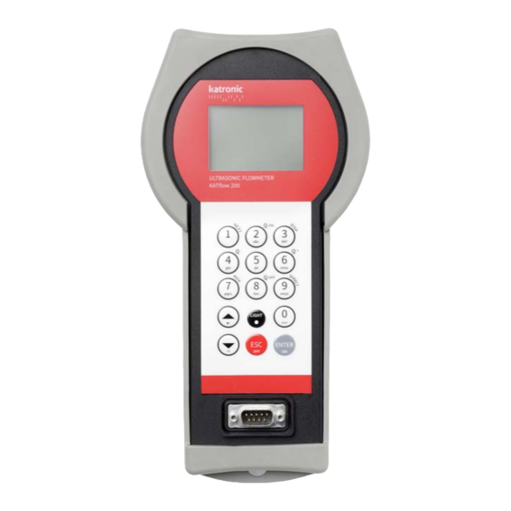
Step 2: Keyboard Familiarisation
K Tflow 200 Quick Start Manual
2. Flow d irection
Reflection Mode
The flowmeter uses an even number
of passes. This is the most conveni-
ent mounting arrangement, as the
transducer separation distance can
be measured very easily and the
sensors can be accurately aligned.
Use whenever possible (Pic. 3).
Diagonal Mode
Signal travels on an odd number of
passes through the pipe.
pass can be used for larger pipes
and for dirty/aerated liquids where
greater signal attenuation can occur.
The sensor distance on this moun-
ting configuration can be negative
(sensors overlapping) (Pic. 4).
NEXT
• Show
(1) available item
Q
•
(2) = Start totaliser function
ON
DISP
• Show next
lay (3)
Q
•
(8) = Stop totaliser function
OFF
DIRECT
•
(9) access to trend plot
UP
• Move menu/selection item
DOWN
• Move menu/selection item
ESC
•
ape entry without saving
OFF
Switch device
(press > 2 sec.)
ENTER
•
selection with saving
ON
Switch device
(press > 2 sec.)
Step 3: Quick Start M enu and Setup Wizard
• The flowmeter can be prepared for measurement with the
Wizard
as found in the
single
www.katronic.co.uk
K Tflow 200
Quick Start Manual
Quick Start
menu.
t first power on and the boot se-
Main Menu
quence, the
is displayed.
UP
DOWN
Use the
and
cursor keys to
Quick Start
select
and confirm by
ENTER
pressing
.
Setup Wizard
Select
to set up the flow-
meter for measurement. If the sensors
are recognised, the serial number will
be shown. If not, the type can be selec-
ted.
Select the main measurement unit
using the cursor keys and confirm
ENTER
with
. This unit will be diplayed
in the middle of the measurement
OFF
screen. Selecting
deactivates the
measurement channel.
Select the pipe material using the cur-
ENTER
sor keys and confirm with
Enter the outer pipe diameter us-
ing the keypad and confirm with
ENTER
UP
. Use
key as backspace to
correct for entry errors. If "0" is
entered and confirmed, an additional
screen appears that allows entry of
the circumference. Press
confirm.
Enter pipe wall thickness using the
ENTER
keypad and confirm with
UP
key as a backspace to correct for
entry errors.
Select fluid using cursor keys. Con-
ENTER
firm by pressing
.
Enter the fluid temperature using the
keypad. Confirm by pressing
UP
Use
key as a backspace to correct
for entry errors.
Select pipe liner material using cursor
keys and confirm by pressing
If a liner material is chosen, an additi-
onal screen appears that allows entry
of liner thickness.
Setup
.
ENTER
to
. Use
ENTER
.
ENTER
.
1/2
Advertisement
Table of Contents

Related Manuals for Katronic KATflow 200


Summary of Contents for Katronic KATflow 200
- Page 1 If a liner material is chosen, an additi- Switch device (press > 2 sec.) ENTER onal screen appears that allows entry • selection with saving of liner thickness. Switch device (press > 2 sec.) K Tflow 200 Quick Start Manual www.katronic.co.uk...
- Page 2 Two further measurement units can be assigned Main Menu to this screen by going to Output Display © Copyright Katronic Technologies Ltd. 2015 | Issue: QS_KF200_V51EN_1509 | ll rights reserved.
Need help?
Do you have a question about the KATflow 200 and is the answer not in the manual?
Questions and answers