Table of Contents
Advertisement
Quick Links
Advertisement
Table of Contents

Subscribe to Our Youtube Channel
Related Manuals for Maretron ALM100-01

Summary of Contents for Maretron ALM100-01
- Page 1 ® ® ALM100 Alarm Module User’s Manual Revision 1.1 Revision 1.1 Page i...
- Page 2 ALM100 User's Manual Revision History Revision Description Original document Added cautions about using red Loctite and acetone cleaners Added information about Instance parameter Corrected installation template Corrected PGN numbers in specification tables Updated firmware revision number Page ii Revision 1.1...
-
Page 3: Table Of Contents
Technical Support ....................... 10 Installation Template ......................11 Maretron (2 Year) Limited Warranty ..................12 Table of Figures Figure 1 – Mounting the ALM100 into an Electrical Box ............3 Figure 2 – Flush Mounting the ALM100 Directly to a Wall ............4 ... -
Page 4: Introduction
Completely waterproof, the Alarm Module can be mounted inside or outside the vessel. The Maretron ALM100 is designed to operate within the harsh demands of the marine environment. However, no piece of marine electronic equipment can function properly unless installed, configured, and maintained in the correct manner. -
Page 5: Alm100 Accessories
Maretron offers the following accessories for the ALM100: • CP-WH-ALM100 ALM100 White Faceplate 1.4 Quick Install Installing the Maretron ALM100 involves the following five steps. Please refer to the individual sections for additional details. 1. Unpack the box (Section 2.1) 2. Choose a mounting location (Section 2.2) 3. -
Page 6: Mounting The Alm100
® ® 2.3 Mounting the ALM100 The ALM100 is designed to be mounted in an ANSI/NEMA WD 6 electrical switch box, but it may also be mounted directly into a wall. If mounting the ALM100 into an electrical box, which can in turn be surface-mounted onto a wall or bulkhead, attach the ALM100 securely to the electrical box using the included mounting screws or other fasteners as shown in Figure 1 below. -
Page 7: Connecting The Alm100
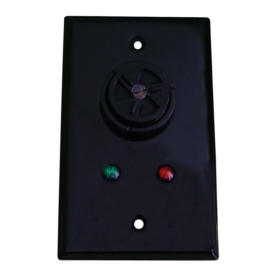
ALM100 User's Manual ALM100 Faceplate NMEA 2000 Cable (not included) Faceplate Gasket ALM100 Mounting Screws (x2) Faceplate Sounder Gasket Mounting Screws (x2) Volume Control Baffle Plate Sounder Collar ALM100 Alarm Module Volume Control Shutter Volume Control Screw Figure 2 – Flush Mounting the ALM100 Directly to a Wall The following instructions apply wither mounting the ALM100 into an electrical box or to a wall: 1) Connect the NMEA 2000 cable to the connector on the ALM100 Alarm Module 2) Using the included ALM100 mounting screws, mount the ALM100 Alarm Module to the... -
Page 8: Checking Connections
ALM100 test function on an appropriate NMEA 2000 display, such as the Maretron DSM250. If the alarm does not sound and flash the red LED during testing, please refer to Section 4, “Troubleshooting”. 2.5 Configuring the ALM100 The ALM100 will sound alarms received over the NMEA 2000 network as it is shipped from the factory;... -
Page 9: Instance
This field allows a display device such as Maretron N2KView or a DSM250 to select different annunciators for sounding alarms for different alert types. For instance, an alert specific to engine operation may only sound in the engine room, pilot house, and crew quarters, while a general alarm would sound throughout the ship. -
Page 10: Installation Description
This configuration option will allow you to program the values of these fields. 3 Maintenance Regular maintenance is important to ensure continued proper operation of the Maretron ALM100. Perform the following tasks periodically: • Clean the unit with a soft cloth. Do not use chemical cleaners as they may remove paint or markings or may corrode the ALM100 enclosure or seals. - Page 11 ALM100 User's Manual The ALM100 does not Ensure that the ALM100 is properly connected and powered as sound when expected. described in the preceding section. Use the “Test Annunciator” function of the DSM250 display to verify that the ALM100 is receiving messages, as described in section 2.5.3.
-
Page 12: Technical Specifications
® ® 5 Technical Specifications As Maretron is constantly improving its products, all specifications are subject to change without notice. Maretron products are designed to be accurate and reliable; however, they should be used only as aids to navigation and not as a replacement for traditional navigation aids and techniques. -
Page 13: Technical Support
® ® 7 Installation Template Please check the dimensions before using the following diagram as a template for drilling the mounting holes because the printing process may have distorted the dimensions. Figure 4 – Mounting Surface Template Revision 1.1 Page 11... -
Page 14: Maretron (2 Year) Limited Warranty
Maretron’s option, of any product not meeting the above limited warranty and which is returned to Maretron; or if Maretron is unable to deliver a replacement that is free from defects in materials or workmanship, Purchaser’s payment for such product will be refunded.
Need help?
Do you have a question about the ALM100-01 and is the answer not in the manual?
Questions and answers