Table of Contents
Advertisement
Quick Links
Advertisement
Table of Contents

Related Manuals for Scientific SM6033


Summary of Contents for Scientific SM6033
- Page 1 Precision LCR Meter SM6033 User Manual...
- Page 2 Information in this manual supersede all corresponding previous released material. Scientific continues to improve products and reserves rights to amend part or all of the specifications, procedures, equipment at any time without notice. Ver1.0/0121 Scientific Mes-Technik Pvt.
-
Page 3: Table Of Contents
3.3.1 PARAM ................28 3.3.2 NOM................28 3.3.3 BIN ................28 3.3.4 HIGH/LOW ..............29 3.3.5 COUNT ................29 3.3.6 AUX ................29 3.3.7 OUT ................29 <LIST SWEEP DISP> .............29 3.4.1 Sweep mode ..............30 3.4.2 FREQ (Hz) ..............31 3.4.3 Cp[F] D[ ] ..............31 SM6033 3/140... - Page 4 3.9.2 Test parameter ...............52 3.9.3 Sweep parameter setup ...........53 3.10 TRACE SWEEP SETUP ............54 3.10.1 Function.................54 3.10.2 Level ................54 3.10.3 DC Bias ................55 3.10.4 Trace ................55 3.10.5 Range ................55 3.10.6 Scale ................55 3.10.7 Frequency ..............55 3.10.8 Speed ................55 SM6033 4/140...
- Page 5 Operation example of testing capacitance by multi-frequency list sweep ..................72 Operation example of load correction ........75 Chapter 6 Performance and Test ............77 Test function ................77 6.1.1 Parameter and symbol .............77 6.1.2 Test combination .............77 6.1.3 Mathematical operation ............77 SM6033 5/140...
- Page 6 6.4.8 Accuracy of L ..............88 6.4.9 Accuracy of Z ..............88 6.4.10 Accuracy of DCR .............89 Chapter 7 Command Reference .............90 Subsystem commands for SM6033 ..........90 7.1.1 DISPlay subsystem commands ..........90 7.1.2 FREQuency subsystem commands ........92 7.1.3 VOLTage subsystem commands .........93 7.1.4...
- Page 7 7.1.15 COMParator subsystem commands ........116 7.1.16 Mass MEMory subsystem commands ........ 121 GPIB Common Commands ........... 122 Chapter 8 Handler ................125 8.1 Description ................125 8.2 Operation ................125 Chapter 9 Maintenance & Service ............139 Chapter 10 Warrantyr ................140 SM6033 7/140...
-
Page 8: Chapter 1 First Time Operation
——————————————————————————————————————— 1.3 Fuse The instrument has installed fuse, so operators should use the installed fuse of our company. ——————————————————————————————————————— Warning: Be sure that the location of fuse is consistent with power-supplying voltage range before charging. ——————————————————————————————————————— SM6033 8/140... -
Page 9: Environment
Note: When test fixture or cable is notconnected, the instrument will display an unstable test result. 1.6 Warm-up 1) To guarantee the accurate measurement, the warm-up time is no less than 15min. 2) Please not turn on or off instrument frequently, in order to avoid the inner data fluster. SM6033 9/140... -
Page 10: Other Features
Scientific 1.7 Other features 1) Power: consumption power≤80VA. 2) Dimension (W*H*D): 430mm*185mm*473mm 3) Weight: About 13kg. SM6033 10/140... -
Page 11: Chapter 2 Introduction
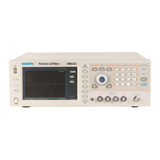
Scientific Chapter 2 Introduction In this chapter, the basic operation features of SM6033 series are described. Please read the content carefully before using SM6033 series instruments, thus you can learn the operation of SM6033. 2.1 Introduction to front panel Figure 2-1 shows the front panel of SM6033. - Page 12 22) Knob for menu selection and numeric input This knob is used to move the cursor, select and set parameters. 23) Confirmation key This key is used to end the data input, confirm and save the data input through knob. 24) Ground terminal SM6033 12/140...
-
Page 13: Introduction To Rear Panel
The function definition varies with different pages. 27) POWER Power switch 2.2 Introduction to rear panel Figure 2-2 shows the rear panel of SM6033. 9 1 0 H A N D L E R I E E E - 4 8 8... -
Page 14: Introduction To Display Zone
The ground terminal is connected with instrument casing, available for protecting or shielding ground connection. 2.3 Introduction to display zone SM6033 has a 65k, 7-inch TFT display. The display screen is divided into the following zones: 1) Display page name Indicates name of the currently displayed page. -
Page 15: Main Menu Keys And Corresponding Displayed
<CORRECTION> <LIMIT TABLE> <LIST SETUP> <TRACE SETUP> <TOOLS> 2.4.3 [SYSTEM] This key-[SYSTEM] is used to enter into the system setup page. The following soft keys will be available: <SYSTEM SETUP> <LAN SETUP> <HANDLER SETUP> <DEFAULT SETTINGS> <SYSTEM REST> SM6033 15/140... -
Page 16: Basic Operation
Scientific 2.5 Basic Operation Basic operation of SM6033 is as follows: Use menu keys ([DISP], SETUP], [SYSTEM]) and soft keys to select the desired page. Use cursor keys ([←][→]) and the slide switch to move the cursor to the desired zone. When the cursor moves to a specified zone, the zone will become reverse expression. - Page 17 [ENTER] to enter into the page of main menu. ——————————————————————————————————————— Note: The instrument has a default password-2829. In your practical use, you can change it and set your own one. Please see <SYSTEM> section for more information. SM6033 17/140...
-
Page 18: Chapter 3 Introduction To [Disp]
When the LCR function is applied, press [DISP], the <MEAS DISPLAY> page will be displayed on screen as shown in the following figure. SM6033-301 On this page, the test result is displayed in upper-case character. The measurement control parameters can be set in this page:... -
Page 19: Test Function
Scientific 3.1.1 Test function In a measurement period, SM6033 can test four parameters for an impedance component: two primary parameters and two secondary parameters. Parameters that can be tested are as follows: Primary parameters |Z| (Module of impedance) |Y| (Module of admittance) - Page 20 8) Press Y—…→, the following parameters will be shown for your choice. ← Press the soft key corresponding to your desired parameter. Then press ← to return to upper soft key menu. 9) Press R—…→, the following parameters will be shown for your choice. Rp-Q SM6033 20/140...
-
Page 21: Test Range
Measurement range should be selected in accordance with the impedance value of the tested LCR component. SM6033 has 9 AC measurement ranges: 10 , 30 , 100 , 300 , 1k , 3k , 10k , 30k , 100k . -
Page 22: Test Level
When using [ENTER] to input frequency, the default unit is Hz. 3.1.4 Test level The measurement level of SM6033 can be set according to the RMS value of sine wave signal. The frequency of sine wave signal is the test frequency which is generated by inner oscillator. -
Page 23: Dc Bias
DCR, the bias zone will display “---”. Operation steps for setting DC bias: SM6033 provides two methods to set the DC bias. The first one is to use soft keys, while the second one is to input data by numeric keys. -
Page 24: Test Speed
The test result of SM6033 is displayed as 6 floating-point digits. Decimal point lock function can make SM6033 output the test result in fixed way. Meanwhile this function can change the displayed digits of test result. This displayed result can... -
Page 25: Save Lcr Test Result By U Disk
3) LIST SWEEP: list, function, function parameter, primary parameter, secondary parameter, status (0 means normal), compare result (-1 means lower than the nominal value, while 1 means higher than the nominal value), line NO., sorting parameter, low limit and high limit; SM6033 25/140... -
Page 26: Bin No. Disp
Scientific SM6033-302 Save function #00003 is the saving times. available MEAS E:\CSV\ is the save path; 005 is the DISP, BIN DISP, LIST fifth, 0121 is the date, QI51200251 is DISP the serial number. 3.2 <BIN NO. DISP> Press [DISP] firstly and then the BIN NO. soft key to enter into <BIN NO. DISP>... -
Page 27: Comparator Function
Open, short and load correction ON/OFF status (CORR) 3.2.1 Comparator function SM6033 has an inserted compare function which can divide DUT to up to 10 bins (from BIN1 to BIN9 and BIN OUT). Users can set 9 pairs of primary parameter limit and one pair of secondary bin limit. -
Page 28: Param
Scientific SM6033-304 The following control parameters can be set on the <BIN COUNT> page. Count function ON/OFF (COUNT) There are 2 zones are displayed in this page: BIN COUNT DISP, COUNT. The function of each zone will be introduced as below. -
Page 29: High/Low
And their test results will be compared with their limits. Press down the menu key [DISP] and then the soft key LIST SWEEP to enter into the <LIST SWEEP DISP> page, shown as below. SM6033 29/140... -
Page 30: Sweep Mode
<LIST SWEEP SETUP>. 3.4.1 Sweep mode The list sweep function of SM6033 can make automatic sweep test for up to 201 points’ test frequencies, test levels or DC bias. Two sweep modes are available on SM6033: SEQ and STEP. -
Page 31: Freq (Hz)
H is higher than the standard, while blank is medium. 3.5 <TRACE SWEEP> Press [DISP] and Choose TRACE SWEEP to enter into the <TRACE SWEEP> page. As shown in figure below: SM6033-306 SM6033 31/140... -
Page 32: Format
Extreme value is the limit value of the primary and secondary parameters. The cursor is a red line. You can observe the value of the primary and secondary parameters in the same frequency by turning the rotary knob. SM6033 32/140... -
Page 33: Trace
Scientific SM6033-307 3.5.4 TRACE Press this key to select TRACE A (display the primary parameters only), TRACE B (display the secondary parameters only), TRACE A+B (display the primary and secondary parameters simultaneously). 3.5.5 POINTS This parameter controls the sacn points. That is, the number of points stepped in the starting and ending conditions. -
Page 34: Meas Setup
Scientific CSV DATA: save the test results in scientific notation to excel form in *.CSV format. SM6033-308 When the user selects the sweep parameter as frequency and impedance, the instrument will display the parameters of some ultrasound components, the detailed parameter is as below: Static capacitance value when C : 1kHz. - Page 35 Deviation Test Reference Value B (REF B) Some zones listed below are as same as that on <MEAS DISP> page, so it is not necessary to introduce in this section, but others will be introduced briefly in the following sections. Test function (FUNCA) SM6033 35/140...
-
Page 36: Trigger Mode
TRIGGER command, SM6033 will execute a test. ——————————————————————————————————————— Note: In the process of testing, when SM6033 receives a trigger signal, it will be ignored. So the trigger signal should be sent after the test is done. When optional HANDLER interface triggers SM6033, the trigger mode is set as EXT. -
Page 37: Bias Current Isolation Function
Execute the following steps and set the bias current isolation function as ON or OFF. 1) Move the cursor to ISO zone, the following soft keys will be displayed. 2) Press ON to turn on the bias current isolation function. SM6033 37/140... -
Page 38: Average
3) Move the cursor to Im zone, the following soft keys will be displayed. 4) Press ON to set the current level monitor function as ON while press OFF to set the current level monitor function as OFF. SM6033 38/140... -
Page 39: Delay Time
Scientific 3.6.6 Delay time SM6033 trigger delay means the delay time from triggering to test-start. Delay function can set the trigger delay time. When the list sweep test function is used, all set delay time will be delayed at each sweep test point. The range of the trigger delay time can be set from 0s to 60s with 1ms as the resolution. - Page 40 MEAS When the reference component is connected with the test terminal, you should press MEAS. Then SM6033 will test the reference component and the test result will be automatically input as the value of REF A. 2) Use MEAS or numeric keys to input the reference value of primary parameter.
-
Page 41: Correction
SM6033 provides two correction modes: the first one is executing open and short correction on all frequency points through interpolation method; the other one is executing open, short and load correction on the frequency point currently set. The following measurement control parameters can be set on the <Correction>... -
Page 42: Open
The real test results of load correction can be tested on FREQ. 3.7.1 OPEN The open correction function of SM6033 can eliminate the error caused by the stray admittance (G, B) parallel-connected with DUT, shown as figure 3-1. Figure 1 Stray Admittance... -
Page 43: Short
4) Press DCR OPEN, SM6033 will test the open-circuit resistance under the DC resistance function. 5) Press ON to turn on the function of open-circuit correction, then SM6033 will perform open-circuit correction calculation in the later testing process. IF FREQ 1~ FREQ 201 are set as OFF, the open-circuit correction data of the current frequency will be calculated by imbedding algorithm. - Page 44 4) Press DCR SHORT, SM6033 will test the short resistance under DC resistance function. 5) Press ON to validate the short correction function. SM6033 will make short correction calculation in latter test. If FREQ 1 ~ FREQ 201 are set as OFF, the short correction function will calculate the short correction data of the current frequency.
-
Page 45: Load
(FREQ 1, FREQ 2 … FREQ 201), the load correction of SM6033 can eliminate the test error. It is obvious that open, short, and load correction can be performed at preset frequencies. The 201 preset frequencies can be set in the setup zones of Spot No. -
Page 46: Load Correction Test Function
Load correction function is only available for calculating transport coefficient. Operation steps for setting load correction test function Refer to section 3.1.1. 3.7.5 Cable length selection The available cable length is 0m, 1m, 2m and 4m. SM6033 46/140... -
Page 47: Limit Table
SETUP> page as the following figure shown. SM6033-311 Compare function can be set on this page. SM6033 can set 9 bin limits of primary parameters and one of secondary parameters. The tested result can be divided into up to 10 bins (BIN 1 to BIN 9 and BIN OUT). If the primary parameter of DUT is within the limit range from BIN1 to BIN9, but the secondary parameter is out of the limit range, in this case the DUT will be sorted into aux bin. -
Page 48: Limit Modes Of Compare Function
Sequential mode Under sequential mode, the range of the test value is the compare limit value. The compare limit value should be set in the order from small to large. Figure 3-3 Tolerance mode and Sequential mode SM6033 48/140... -
Page 49: Set Nominal Value Of Tolerance Mode
3.8.4 Comparator function ON/OFF SM6033 can set 9 bin limits of primary parameters and 1 bin limit of secondary parameters. The tested results can be sorted into 10 bins (BIN 1 to BIN 9 and BIN OUT) at most. -
Page 50: Auxiliary Bin On/Off
DUT will be sorted into the auxiliary bin. ——————————————————————————————————————— Operation steps for setting the auxiliary bin function ON/OFF 1) Move the cursor to AUX, the following soft keys will be displayed. 2) Use above soft keys to set the auxiliary function as ON or OFF. SM6033 50/140... -
Page 51: High/Low
Scientific 3.8.6 HIGH/LOW SM6033 can set bin limits of 9 primary parameters and one secondary parameter. The test results can be sorted into 10 bins at most (BIN 1 to BIN 9 and BIN OUT). The high/low limits of primary parameters can be set in high limit and low limit of bins from BIN 1 to BIN 9. -
Page 52: List Sweep Setup
SM6033-312 The list sweep function of SM6033 can perform auto sweep test for the test frequency, test level or bias voltage of 201 points. On <LIST SWEEP SETUP> page, the following list sweep parameters can be set. -
Page 53: Sweep Parameter Setup
PAGE to lighten the arrow and use the rotary knob to switch the page. In No. zone, press CLEAR TABLE to clear all the data of 201 points. In sweep point zone, press FILL LINEAR or FILL LOG to input the sweep point data automatically. SM6033 53/140... -
Page 54: Trace Sweep Setup
Press [SETUP] and then TRACE SETUP to enter into the <TACE SETUP> page as the following figure shown. SM6033-313 The display function page is used for the setup of trace sweep measurement parameters, including FUNC, MODE, START, STOP and coordination range of primary and secondary parameter. -
Page 55: Dc Bias
3.10.9 Format FORMAT here is to set the sweep format mode, LIN and LOG. Please see details in Chapter 3.5.1 Format. 3.10.10 Trigger TRIG here is to set the sweep trigger mode. Single is the single trigger, while SM6033 55/140... -
Page 56: Mode
9 /+, -/.) and press enter key or ~ select a corresponding unit. NOTE: the END condition should be greater than the START condition, or error message will be displayed on the screen. Also, it should be less than the upper SM6033 56/140... -
Page 57: Coordination Range Settiing
At the same time, the distribution situation of the trace in coordinate system will also be changed. This parameter can help observe and analyze the trend of the sweep trace. SM6033 57/140... -
Page 58: Chapter 4 [System] And
Press [System] and then SYSTEM SETUP to enter into the <SYSTEM SETUP> page shown as below. SM6033-401 On this page, most system setup items are displayed, such as instrument main function, beeper, PASS beeper, FAIL beeper, language, theme, PASSWORD, bus mode, GPIB address, TALK only, Bias SRC, baud rate, date/time. -
Page 59: Pass Beep
This zone is used to control and display the current language mode of the operating instrument. Operation steps for setting language 1) Move the cursor to Language, the following soft keys will be displayed. English This soft key is used to select English as the operation language. SM6033 59/140... -
Page 60: Theme
DISP and SYSTEM. 4.1.8 BUS MODE This mode is used to select RS232C, GPIB, LAN, USBTMC or USBCDC. Operation steps for setting bus mode 1) Move the cursor to Bus, the following soft keys will be displayed. SM6033 60/140... -
Page 61: Gpib Addr (Reserved Function)
Bias source is used to select the DC bias power. The instrument provides 3 kinds of bias source as shown below: INT mode The standard DC bias voltage source is from -10V to +10V and the DC bias current source is from 0 to 100mA. SM6033 61/140... -
Page 62: Baud Rate
This soft key is used to increase the baud rate. DECR ( ( ( ( ) ) ) ) This soft key is used to decrease the baud rate. 4.1.13 DATE/TIME When moving to the time zone, user should input the password to enter. SM6033 62/140... -
Page 63: Lcr
Scientific 4.2 LCR <FILE MANAGE> SM6033 series instrument can save the user-set parameter to the nonvolatile memory in the form of file, so when use the same setting next time user can load a corresponding file to obtain the parameter set and used last time. By doing so, it can save the time of setting parameter and improve the production efficiency. -
Page 64: U-Disk Manage Performance
Page format currently displayed 4.2.2 U-disk manage performance As described above, SM6033 has a standard configuration of USB HOST interface, so the external U-disk can be used as the memory media. In this condition, it breaks the memory limit of 200 groups of *.LCR files. Meanwhile those files can be copied to IBM PC or compatible desk-top computer, laptop with USB interface to reach the infinite extension. -
Page 65: Operation Steps For File Management
7) Use numeric keys to input the current file name and press [ENTER]. Then SM6033 will save the control and setting parameters as a file in this name. C. Load the control and setting parameters from a file by the following steps 1) Press File Manage, the file list and the following soft keys will be displayed. - Page 66 5) When copying the files, the progress bar will prompt the replication schedule. When the progress bar disappears, the copy operation is finished. SM6033-403 NOTE: Please make sure that your U-disk meets the standard that described in this chapter and no write-read protection.
-
Page 67: Chapter 5 Execute Lcr Operation And Some Examples
MEAS LOAD will be displayed in the soft key zone. n) Press OFF to turn off the point-frequency correction function of FREQ. 5.1.2 Point-frequency correction This function will gain better results in single-frequency test. If the test frequency is 5.5kHz, SM6033 67/140... -
Page 68: Correct Connection Of Dut
0.1%), before connecting to DUT, it is recommended to connect Hcur, Hpot and Lpot, Lcur (Two terminal test). In the test with high accuracy requirement, using Kelvin test fixture (standard accessory) will gain better results than using test leads. When Kelvin test lead is SM6033 68/140... -
Page 69: Eliminate The Influence Of Stray Impedance
“-”, “Lc” or “Lp”. Warning: Before testing, please discharge the tested polarity component so as to avoid the damage to the instrument. 5.3 Eliminate the influence of stray impedance Shielding ground Test terminal Metal conductor Figure 5-1 Influence of stray capacitance SM6033 69/140... -
Page 70: Operation Example For Testing Inductance
By this way, the magnetic fields produced by these currents can be mutually offset and further eliminate the influence of mutual inductance coupling on test results. 5.4 Operation example for testing inductance Test Condition Function: Ls-Q Frequency: 5.5kHz Level: 1.5Vrms Internal impedance: 100 Operation steps 1) Turn on the instrument. SM6033 70/140... - Page 71 100 as the signal internal impedance. 3) Connect the test fixture (SMA26005) to the test terminals of SM6033. 4) Execute correction (To avoid the influence of stray impedance on measurement accuracy, Open/ Short correction must be operated) (refer to 5.1.2 “Point-frequency correction”)
-
Page 72: Operation Example Of Testing Capacitance By Multi-Frequency List Sweep
Scientific SM6033-501 7) If the test result is obviously incorrect, please check the following items. a) Check the tested inductance is in good connection with the test fixture or not. b) Check the test fixture is in good connection with the test terminals of the instrument or not. - Page 73 µ, m. Press [ENTER], this zone will be changed as 100.000µ and the cursor will automatically move to the high limit zone of sweep point 2. p) Press [0][.][0][0][0][3], +0.0003 will be displayed in the prompt SM6033 73/140...
- Page 74 Press [SYSTEM] to enter into the <System Setup> page. Move the cursor to the FAIL BEEP zone to select HIGH LONG. 4) Mount the test fixture (SMA26005) to the test terminals of SM6033. 5) Execute correction function (To avoid the influence of the stray impedance on the measurement accuracy, it is necessary to execute open/short correction (refer to chapter 5.1.1 Sweep Correction).
-
Page 75: Operation Example Of Load Correction
µ, m and k. Press [ENTER], this zone will be changed as 0.00050. p) Move the cursor to FREQ. The following soft keys will be displayed: ON, OFF, MEAS OPEN, MEAS SHORT and LOAD. SM6033 75/140... - Page 76 The load correction is only valid for the components with the same specification. If the specification is changed, it is required to redo load correction. SM6033 76/140...
-
Page 77: Chapter 6 Performance And Test
Auto, Manual (Hold, increase and decrease) 6.1.6 Trigger Internal, external and manual Internal: Test DUT constantly and display the result Manual: Press TRIGGER to test once then the result will be displayed. External: After HANDLER receiving “start” signal, perform a measurement and SM6033 77/140... -
Page 78: Delay Time
Delay time: time from trigger to start. 0 to 60s are programmable with a resolution of 1ms. 6.1.8 Connection modes of test terminals SM6033 adopts 4-terminal test method. HD(Hcur): current sample high terminal LD(Lcur): Current sample low terminal HS(Hpot) v oltage sample high terminal :... -
Page 79: Signal Mode
Parameter Measurement display range 0.00001µH 99.9999kH 、 ~ 0.00001pF 9.99999F ~ D CR 0.00001 99.9999M 、 、 、 ~ 0.00001µs 99.9999S 、 、 ~ 0.00001 — 9.99999 0.00001 — 99999.9 -179.999° 1 79.999° ~ θ -3.14159 3.14159 ~ SM6033 79/140... -
Page 80: Dc Bias Voltage Source
Q ≤ 0.1 : ( ) When D ≥0.1, accuracy factor A of L, C, X, B should be multiplied by When Q ≥0.1, accuracy factor A of R, G should be multiplied by SM6033 80/140... -
Page 81: D Accuracy
C with the unit [F]. is the value of tested L with the unit [H]. is the accuracy of D. F is test frequency. 6.3.6 Rp accuracy when D v alue of tested D ≤ 0.1 ( ) SM6033 81/140... -
Page 82: Rs Accuracy
C with the unit [F]. is the value of test L with the unit [H]. is the accuracy of D F is test frequency 6.3.8 Accuracy factor Figure A Basic measurement accuracy factor A SM6033 82/140... - Page 83 In figure A, two values of basic measurement accuracy A are included in each frame. For example, the two values in the middle frame are 0.05(top) / 0.1(bottom). When the test speed is MEDIUM or SLOW, select the value in the top, such as 0.05. SM6033 83/140...
- Page 84 Table A. Figure B Level correction factor A curve Table B Impedance rate factors: K Speed Frequency − × − fm≤1.2kHz × Medium 1.2kHz<fm − × Slow ≤8kHz − × 8kHz<fm − × ≤150kHz SM6033 84/140...
- Page 85 1+5×fm 1+10×fm 100kHz<fm≤300kHz 1+2×fm 1+4×fm 300kHz<fm≤1MHz 1+0.5×fm 1+1×fm Where, f is the test frequency and the unit is [MHz]. Table E calibrated interpolating factor K Test frequency Direct calibrated frequency (listed in Table F) Other frequency 0.0003 SM6033 85/140...
-
Page 86: Dcr Accuracy
All tests should be performed under the working condition listed in Chapter 1. In this part, only the main indexes are listed. Users can make test under the specified condition mentioned in this manual. Performance test can be worked in the warm up conditions discussed in Chapter 1. SM6033 86/140... -
Page 87: The Used Instruments And Devices
Adjust multimeter in AC voltage range, where one test cable is connected to H and the other is connected to ground terminal. Change level as: 10mV, 20mV, 100mV, 200mV, 1V, 2V, the reading should meet the demand of test signal level in this chapter. SM6033 87/140... -
Page 88: Frequency
Open and short correction should be made before testing. Connect standard inductors: 100µH, 1mH, 10mH, 100mH and change the frequency. The error between reading and nominal value should be in the range ruled in this chapter. 6.4.9 Accuracy of Z Test condition: Function Z-θ SM6033 88/140... -
Page 89: Accuracy Of Dcr
Short correction should be made before testing. Connect standard DC resistors: 0.1 , 1 , 10 , 100 , 1k , 10k , 100k . The error between reading and nominal value should be in the range ruled in this chapter. SM6033 89/140... -
Page 90: Chapter 7 Command Reference
The signs in this manual are as follows: NR1: integer, e.g.:123 NR2: fix-point number, e.g.: 12.3 NR3: floating-point number, e.g.: 12.3E+5 NL: carriage key, integer: 10 E ND: EOI signal in IEEE-488 ˆ 7.1 Subsystem commands for SM6033 D ISPlay ● O RESister ● T RIGger ●... - Page 91 Set the display page as the file list page. For example: WrtCmd(“DISP:PAGE MEAS”), Set the display page as the LCR measurement display page. Query syntax: DISPlay:PAGE? Return format: <page name><NL^END> <page name> can be set as the following items: SM6033 91/140...
-
Page 92: Frequency Subsystem Commands
Return format: <font><NL^END> <font> can be the following information: LARGE TINY 7.1.2 FREQuency subsystem commands The FREQuency subsystem commands are mainly used to set the measurement frequency of the instrument. The :FREQuency query returns the current measurement frequency. SM6033 92/140... -
Page 93: Voltage Subsystem Commands
CURRent subsystem commands The CURRent subsystem commands are mainly used to set the measurement current. The CURRent? query returns the current measurement current. Command syntax: <value> CURRent Where, <value> NR1, NR2 or NR3 data format followed by MA. SM6033 93/140... -
Page 94: Amplitude Subsystem Commands
The Output RESistor subsystem commands are mainly used to set the output internal resistor mode. The Output RESistor? query returns the current output internal resistance status. Command syntax: ORESistor For example: WrtCmd (“ORES 30”) Set the output internal resistance is 30 OHM. Query syntax: ORESistor? Return format: <NR1><NL^END> SM6033 94/140... -
Page 95: Output Subsystem Commands
DC bias source is used, or unused. The OUTPut:DC:ISOLation command is used to set the DC isolation function of the 100mA/10V DC bias source as ON or OFF. The OUTPut:DC:ISOLation? query returns the current status of the DC isolation function. Command syntax: OUTPut:DC:ISOLation SM6033 95/140... -
Page 96: Bias Subsystem Commands
For example: WrtCmd (“BIAS:STATe 0”) Set the DC bias function as OFF. Query syntax: BIAS:STATe? Return format: <NR1><NL^END> The BIAS:VOLTage command is used to set the internal bias voltage. The BIAS:VOLTage? query returns the current bias voltage. Command syntax: SM6033 96/140... -
Page 97: Function Subsystem Commands
For example: WrtCmd (“BIAS:CURR MIN”) Set the DC bias current as 0A. Query syntax: BIAS:CURRent? Return format: <NR3><NL^END> 7.1.9 FUNCtion subsystem commands The FUNCtion subsystem commands are mainly used to set measurement functions, range, current/voltage monitor ON/OFF, deviation display mode, nominal setting. Command tree: SM6033 97/140... - Page 98 FUNCtion:IMPedance? query returns the current function parameters. Command syntax: FUNCtion:IMPedance <function> <function> can be one of the following items. Set the function as Cp-D LPRP Set the function as Lp-Rp Set the function as Cp-Q Set the function as Ls-D SM6033 98/140...
- Page 99 Command syntax: ON (1) FUNCtion:IMPedance:RANGe:AUTO OFF (0) Where, Character 1 (49) is equal to ON. Character 0 (48) is equal to OFF. For example: WrtCmd (“FUNC:IMP:RANG:AUTO ON”) Set the automatic range as ON. Query syntax: FUNCtion:IMPedance:RANGe:AUTO? Return format: <NR1><NL^END> SM6033 99/140...
- Page 100 Percent deviation display Real value display Where, <n> is Character 1 (49) is equal to the nominal value of primary parameter. Or character 2 (50) is equal to the nominal value of the secondary parameter. For example: WrtCmd (“FUNC:DEV1:MODE ABS”) SM6033 100/140...
-
Page 101: List Subsystem Commands
Character 1 (49) or haracter 2 (50)is equal to the nominal values of the primary and secondary parameters. For example: WrtCmd (“FUNC:DEV1:REF:FILL”) 7.1.10 LIST subsystem commands The LIST subsystem commands are mainly used to set the list sweep function, sweep points, sweep mode, sweep limits. Command tree: SM6033 101/140... - Page 102 The LIST:VOLTage command is used to clear the original voltage of the each sweep point and reset the voltage. The LIST:VOLTage? query returns the current voltage of each sweep point. Command syntax: LIST:VOLTage<value>[,<value>*] NOTE: * part means 201 sweep points at most can be set. SM6033 102/140...
- Page 103 NOTE: * part means 201 sweep points at most can be set. Where, <value> is NR1, NR2 or NR3 data format. For example: WrtCmd (“LIST:BIAS:VOLT 1.5V”) Set the DC bias voltage of sweep point 1 as 1.5V. Query syntax: LIST:BIAS V OLTage? : Return format: <NR3>[,<NR3>*]<NL^END> SM6033 103/140...
- Page 104 40mA. Query syntax: LIST:BIAS:CURRent? Return format: <NR3>[,<NR3>*]<NL^END> NOTE: SM6033 instrument has installed a 10V/100mA internal DC bias current source. If 1A DC source is required, please install an external source. The instrument can be used with SM6027A DC Bias Source (providing DC current from 0 to 20A).
-
Page 105: Aperture Subsystem Commands
<value> 1 to 255 in NR1 For example: WrtCmd (“APER MED, 55”) Query syntax: APERture? Return format: FAST , <NR1><NL^END> SLOW 7.1.12 TRIGger subsystem commands The TRIGger subsystem commands are mainly used to set the instrument trigger source, trigger delay and trigger measurement. SM6033 105/140... - Page 106 Triggered by pressing TRIGGER. For example: WrtCmd (“TRIG:SOUR BUS”) Query syntax: TRIGger:SOURce? Return format: <NL^END> HOLD The TRIGger:DELay command is used to set the delay time after triggering. The TRIGger:DELay? query returns the current delay time. Command syntax: <value> TRIGger:DELay SM6033 106/140...
-
Page 107: Fetch? Subsystem Commands
For example: WrtCmd (“TRIG:DEL 5s”) Set the delay time as 5s. Query syntax: TRIGger:DELay? Return format: <NR3><NL^END> 7.1.13 FETCh? subsystem commands The FETCh? subsystem commands are mainly used to direct SM6033 to input a measurement result. Command tree: FETCh [:IMP]? :Source MONitor... - Page 108 On list sweep display page, the ASCII data output format is shown as below, that is, the return-circuit replaces sweep point number. , SN.NNNNNESNN SN.NNNNNESNN SN NL^END , , , <DATA A> <DATA B> <Status> <Judge> Figure 6 ASCII format 2 (list sweep) SM6033 108/140...
- Page 109 Meanwhile when the measurement serial number is equal to or larger than 5 (that is to say testing leakage inductance LK and DC resistance DCR), no secondary parameter will be displayed but directly display the status. The status format is : SN: +/_, N is 0/1. SM6033 109/140...
-
Page 110: Correction Subsystem Commands
Scientific Status Description Pass High 7.1.14 CORRection subsystem commands The CORRection subsystem commands are mainly used to set the correction function, OPEN, SHORT, LOAD. Command tree: SM6033 110/140... - Page 111 :STATe ON (1) OFF (0) :SHORt :STATe ON (1) OFF (0) :LOAD :STATe ON (1) OFF (0) :TYPE CPRP CSRS LPRP LSRS :SPOT<n> :STATe ON (1) OFF (0) :FREQuency <value> :OPEN :SHORt :LOAD :STANdard <REF.A>,<REF.B> :USE :DATA? :CLEar SM6033 111/140...
- Page 112 O PEN:STATe? query returns the current open correction : status. Command syntax: CORRction:OPEN:STATe Where, 1 (decimal 49) is equal to ON. 0 (decimal 48) is equal to OFF. For example: WrtCmd (“CORR:OPEN: STAT ON”) Query syntax: CORRection:OPEN:STATe? Return format: <NR1><NL^END> SM6033 112/140...
- Page 113 Set the function as Ls-Q CPRP Set the function as Cp-Rp LSRS Set the function as Ls-Rs Set the function as Cs-D Set the function as R-X Set the function as Cs-Q Set the function as Z-θ ◦ SM6033 113/140...
- Page 114 For example: WrtCmd (“CORR:SPOT1:FREQ 2KHZ”) Set the frequency of frequency spot 1 as 2KHZ. NOTE: <value> should be ranged from 20HZ to 300KHZ (SM6033A), 20HZ to 1MHZ (SM6033C) or return format will report errors. Query syntax: CORRection:SPOT<n>:FREQuency? Return format: <NR3><NL^END> SM6033 114/140...
- Page 115 For example: WrtCmd (“CORR:SPOT1:LOAD:STAN 100.7, 0.0002”) Query syntax: CORRection:SPOT<n>:LOAD:STANdard? Return format: <NR3><NL^END> The CORRection:USE:DATA? query returns the OPEN/SHORT/LOAD correction measurement data of specific frequency spot 1, 2 … 201. Command syntax: CORRection:USE:DATA? Return format: <open1 A>,<open1 B>,<short1 A>,<short1 B>,<load1 A>,<load1 B>, SM6033 115/140...
-
Page 116: Comparator Subsystem Commands
The CORRection:CLEar command is used to clear the correction data of all the correction points. Command syntax: CORRection:CLEar 7.1.15 COMParator subsystem commands The COMParataor subsystem commands are used to set the bin comparator function including ON/OFF setting, Limit table setting. Command tree: SM6033 116/140... - Page 117 0 (decimal 48) is equal to OFF. For example: WrtCmd (“COMP ON”) Query syntax: COMParator[:STATe]? Return format: <NR1><NL^END>. The COMParator:MODE command is used to set the comparator mode. The COMParator:MODE? query returns the current mode. Command syntax: ATOLerance COMParator:MODE PTOLerance SEQuence Where, SM6033 117/140...
- Page 118 (this function is valid only when the limit mode is set as the sequential mode.). The COMParator:SEQuence:BIN? query returns the current high and the low limits of each bin. Command syntax: COMParator:SEQuence:BIN <BIN1 low limit>, <BIN 1 high limit>, <BIN2 high limit>, …, <BINn high limit> SM6033 118/140...
- Page 119 For example: WrtCmd (“COMP:ABIN ON”) Query syntax: COMParator:Auxiliary BIN? Return format: <NR1><NL^END> The COMParator:SWAP command is used to set the swap mode ON or OFF. For example: the original function parameter is Cp-D, after the SWAP mode is set as SM6033 119/140...
- Page 120 For example: WrtCmd (“COMP:BIN:COUN ON”) Query syntax: COMParator:BIN:COUNt[STATe]? Return format: <NR1><NL^END> The COMParator:BIN:COUNt:DATA? query returns the current comparison result of the bin count. Query syntax: COMParator:BIN:COUNt:DATA? Return format: <BIN1 count>, <BIN2 count>, …, <BIN9 count>, <OUT OF BIN SM6033 120/140...
-
Page 121: Mass Memory Subsystem Commands
<value> is the file number ranging from 0 to 39 (NR1). <string> can be ASCII character string (maximum length is 16). For example: WrtCmd (“MMEM:STOR:STAT 1, “Resistor meas””) or WrtCmd (“MMEM:STOR:STAT 1”), IF “,”<string>”” has not been input, the default file name will be stored. SM6033 121/140... -
Page 122: Gpib Common Commands
Date of the software version (2016-01-11) For example: WrtCmd(“*IDN?”); The *TST? query executes an internal self test and returns the test result as the sum of all existing errors codes. If there are no error SM6033 returns 0. Query syntax: *TST? Return format: 0<NL^END>... - Page 123 The *ESR? query returns the contents of the standard event status register. Query syntax: *ESR? Return format: <value><NL^END> Where, <value> NR1 format: decimal expression for contents of the standard event status register. Descriptions for each bit of the standard event status register SM6033 123/140...
- Page 124 For example: WrtCmd (“*STB?”) The *OPC command equals to set the OPC bit of the standard event status register when SM6033 finishes all parameter measurements. Ever since all pending operations have been completed, this command will inform the instrument to add a ASCII number “1” (decimal number: 49) into the output buffer.
-
Page 125: Chapter 8 Handler
Chapter 8 Handler The SM6033 provides the Handler interface for you. The interface is mainly used for the output of the sorted result. The interface offers the communication signal and the signal for the output of the sorted result. The separator result is corresponding to the output of BIN 10. - Page 126 /BIN8 /BIN9 /OUT /AUX /EXT.TRIG External trigger: when the trigger mode is EXT.TRIG, SM6033 will be triggered by the positive-edge in this pin. External DC voltage 2: EXT.DCV2 The DC provider pin for the optoelectronic coupling signal(/EXT_TRIG, /KeyLock, /ALARM ,...
- Page 127 BIN 5 SREJ A UX ( ) ( ) BIN 6 BIN 7 BIN 8 BIN 9 ( O UT ) The secondary parameter Figure 1 the /PHI / PLO / SREJ signal distribution for BIN comparison , , SM6033 127/140...
- Page 128 EXT.DCV2 COM2 COM1 COM1 COM1 Note: the signal to /BIN1 - /BIN9, /OUT, /AUX, /PHI, /PLO and /SREJ in the list sweep comparison is different from that in the BIN comparison. Figure 2 the pin definition for HANDLER SM6033 128/140...
- Page 129 (figure 4). /AUX shows PASS/FAIL judgement. When a sweep test is finished, these signal will be the output signal. Control /INDEX(analog test finished), /EOM(the test ended). The timing is below when /INDEX and /EOM are effective : SM6033 129/140...
- Page 130 /EOM is effective. /EOM Test ended : w hen the test is finished and the compared results are : effective, this signal is effective. STEP : When the test of every sweep point is finished, /EOM is SM6033 130/140...
- Page 131 The definition is the same to that of the comparison. /BIN1 /BIN2 /BIN3 /BIN4 /BIN5 /BIN6 /BIN7 /BIN8 /BIN9 /OUT the measurement data the high limit the good area the low limit the sweep point Figure 4 the signal area of the list sweep comparison SM6033 131/140...
- Page 132 The output voltage on every line is set by the pull-up resistance on the HANDLER interface board. The pull-up resistance is connected to the internal voltage (+5v). or the external SM6033 132/140...
- Page 133 HIGH compared Internal pull-up voltage: signal SM6033 GND /BIN1 - /BIN9 /AUX ≤0.5V +5V--+24V EXTV1 : /OUT COM1 /PHI /PLO control signal Internal pull-up voltage :...
- Page 134 Scientific SM6033 134/140...
- Page 135 Internal Power Supply Voltage, the jumping line of Handler interface board must be in short circuit. Considering the anti-interference ability of SM6033, we suggest you to provide and use external +5V power supply as pull-up power supply of optocoupler. Now, the jumping line should be open (factory settings).
- Page 136 Note: The factory default jumper (JP3) is connected to EXTV2, that is, connected to the external power supply, and the pull-up resistor R is 100k. Handler input interface internal diagram Note: The factory default jumper (JP3) is connected to EXTV2, that is, the external power connection is connected. SM6033 136/140...
- Page 137 (2) Set the standard value and the high limit and the low limit in LIMIT TABLE SETUP. Refer to the [DISP key description to see more details. (3) Move the cursor to COMP zone. The softkey area will be displayed: SM6033 137/140...
- Page 138 Note: the following methods can be used to improve the speed: (1)Set the range to the maximum that the capacitance may be, and lock this range. (2)Set Vm: OFF and Im: OFF in the MEAS SETUP page. (3)Test the DUT in the BIN COUNT page. SM6033 138/140...
-
Page 139: Chapter 9 Maintenance, Service
2. Dispatch the instrument (only on the receipt of our advice) securely packed in original packing duly insured and freight paid along with accessories and a copy of the faults details noticed at our Service Center listed on last page of this manual, nearest to you. SM6033 139/140... -
Page 140: Chapter 10 Warrantyr
Scientific Chapter 10 Warranty Scientific warrants the instrument to be free from defects in material and workmanship when used under normal operating conditions in accordance with the instructions given in the manual for a period of 12 (Twelve) months from date of purchase from Scientific or its authorized dealers.
Need help?
Do you have a question about the SM6033 and is the answer not in the manual?
Questions and answers