Table of Contents
Advertisement
Quick Links
Advertisement
Table of Contents

Related Manuals for Scientific SMS3000X


Summary of Contents for Scientific SMS3000X
- Page 1 Spectrum Analyzer SMS3000X User Manual...
- Page 2 Information in this manual supersedes all corresponding previous released material. Scientific continues to improve products and reserves rights to amend part or all of the specifications, procedures, equipment at any time without notice.
-
Page 3: Table Of Contents
Demod ...................... 49 Marker Setup....................... 50 2.3.1 Marker ...................... 50 2.3.2 Marker -> ....................53 2.3.3 Marker Fn ....................55 2.3.4 Peak ......................57 Measurement ...................... 59 2.4.1 Meas......................59 2.4.2 Meas setup ....................60 SMS3000X 3/75... - Page 4 2.6.2 Couple ...................... 72 2.6.3 Help ......................72 2.6.4 Save ......................72 Chapter 3 General Inspection and Troubleshooting ............73 General Inspection ....................73 Troubleshooting....................73 Chapter 4 General Inspection and Troubleshooting ............75 4/75 SMS3000X...
-
Page 5: General Safety Summary
In order to avoid short circuiting to the interior of the device or electric shock, please do not operate the instrument in a humid environment. Do Not Operate in an Explosive Atmosphere. In order to avoid damage to the device or personal injury, it is important to operate the device away from an explosive atmosphere. SMS3000X 5/75... -
Page 6: Safety Terms And Symbols
WARNING Indicates potential injuries or hazards that may happen. CAUTION Indicates potential damages to the instrument or other property that may happen. Symbols on the product. These symbols may appear on the product: Hazardous Protective Warning Earth Chassis Voltage Ground Ground 6/75 SMS3000X... -
Page 7: Spectrum Analyzer Overview
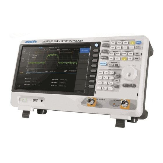
Scientific Spectrum Analyzer overview The SMS3000X series spectrum analyzer has a frequency range from 9 kHz up to 2.1 GHz/3.2 GHz, it is light weight and small size, with a user friendly interface, concise style of display, reliable precision measurement and plenty of RF measurement functions. Applicable to research and development, education, production, maintenance and other related fields, that meets a wider range of application requirements. -
Page 8: Chapter 1 Quick Start
Subjects in this chapter: Appearance and Dimension To Prepare for Use The Front Panel Rear Panel User Interface Menu Operation Parameter Setting To Use the Built-in Help To Use the Security Lock 8/75 SMS3000X... -
Page 9: Appearance And Dimension
Scientific Appearance and Dimension Front View Figure 1- 1 Figure 1- 2 Top View SMS3000X 9/75... -
Page 10: To Prepare For Use
Adjust the supporting legs properly to use them as stands to tilt the Spectrum Analyzer upwards for stable placement as well as easier operation and observation of the instrument. Figure 1- 3 Before adjusting Figure 1- 4 After adjusting 10/75 SMS3000X... -
Page 11: Connect To Ac Power Supply
1.2.2 Connect to AC Power Supply The Spectrum Analyzer accept 100-240V, 50/60/440Hz AC power supply. Please use the power cord provided as accessories to connect the instrument to the power source as shown in the figure below. Figure 1- 5 Power Cord Connection SMS3000X 11/75... -
Page 12: The Front Panel
The Front Panel Figure 1- 6 The Front Panel Table 1- 1 Front Panel Description Description Description User Graphical Interface Numeric Keyboard Menu Control Keys TG Output Function Keys Earphone interface Knob USB Host Arrow Keys Power Switch RF Input 12/75 SMS3000X... -
Page 13: Front Panel Function Keys
Selects the Noise Marker\N dB BW\Freq Counter\Read out of Freq Searches for the Peak Signal and Counts the Peak Frequency Peak Meas Selects the Channel Power\ACPR\Occupied BW\T-Power Used to Choose the Parameters Details of Channel Power\ACPR \Occupied Meas Setup BW\T-Power SMS3000X 13/75... -
Page 14: Front Panel Key Backlight
Spectrum Analyzer provides a numeric keyboard at the front panel (as shown in the figure below). The numeric keyboard which supports the English uppercase/lowercase characters, numbers and common symbols (including decimal point, #, space and +/-) are mainly used to edit file or folder name and set parameters (refer to “Parameter Setting”). 14/75 SMS3000X... - Page 15 When the instrument is in remote mode, use this key to return to local mode. 6.Enter When pressed during parameter editing process, the system will complete the input and insert a default unit for the parameter automatically. SMS3000X 15/75...
-
Page 16: Front Panel Connectors
The analyzer provides AM and FM demodulations. Insert the earphone to the jack to aquire the audio output of the demodulated signal. You can turn on or off the earphone output and adjust the volume via Demod ->Volume. 16/75 SMS3000X... - Page 17 To avoid damage to the instrument, for the signal input from the RF input terminal, the DC voltage component and the maximum continuous power of the AC (RF) signal component can not exceed 50 V and +30 dBm respectively. SMS3000X 17/75...
-
Page 18: Rear Panel
When the external reference is lost or not connected, the instrument switches to its internal reference source automatically and “Ext Ref” on the screen disappears. The [10MHz IN] and [10MHz OUT] connectors are usually used to build synchronization among multiple instruments. 18/75 SMS3000X... - Page 19 If needed, you can use a security lock (not provided with instrument) to lock the analyzer to a desired location. 8. Connect to AC Power Supply The Spectrum Analyzer accept 100-240V, 50/60/440Hz AC power supply. Please use the power cord provided as accessories to connect the instrument SMS3000X 19/75...
-
Page 20: User Interface
Automatically sets the optimal parameters according to the characteristics of the signal USB storage device The identification is displayed when a USB flash drive identification is inserted Menu title Function of the current menu. Menu items Menu items of the current function 20/75 SMS3000X... -
Page 21: Menu Operation
For example, select Center Freq, input the desired figure and press Enter to change the center frequency. 2. state switching Press the corresponding menu key to switch between the sub-options. For example, press Preamp to enable or disable the amplifier. SMS3000X 21/75... - Page 22 7. State Selection Press the corresponding menu key to modify the parameter return to the menu one level up. For example, press Trig Type ->Free Run to select free trigger and the analyzer is in Free Run state at present. 22/75 SMS3000X...
-
Page 23: Parameter Setting
When the parameter is editable (namely when the parameter is selected), you can increase or decrease the parameter value at the specific step using the direction keys. 1) press Frequency -> “Center Freq” 2) Press the up/down Arrow key until the parameter is set to the desired value (100 MHz). SMS3000X 23/75... -
Page 24: To Use The Built-In Help
Then press the key that you want to get help of and the relevant help information will be shown at the center of the screen. 2. Close the current help information When the help information is displayed on the screen, Press the Help button, It will close the help information. Figure 1- 13 help information 24/75 SMS3000X... -
Page 25: To Use The Security Lock
The method is as follows, align the lock with the lock hole and plug it into the lock hole vertically, turn the key clockwise to lock the Spectrum Analyzer and then pull the key out. Figure 1- 14 Security Lock SMS3000X 25/75... -
Page 26: Chapter 2 Front Panel Operation
Scientific Chapter 2 Front Panel Operation This chapter describes in detail the function keys on the front panel and the associated functions. Subjects in this chapter: Basic Settings Sweep and Function Settings Marker Setup Measurement System Shortcut Key 26/75 SMS3000X... -
Page 27: Basic Settings
Range Zero Span, 0 Hz ~ Full Span Nonzero Span, 50 Hz ~ (Full Span -50Hz) Unit GHz\MHz\kHz\Hz Knob Step Span>0, step=Span/200 Span=0, step=RBW/100 Min 1 Hz Direction Key Step CF step Related to Start Freq, Stop Freq SMS3000X 27/75... - Page 28 Full Span Range Zero Span: 0 Hz ~ Full Span Nonzero Span: 100 Hz ~ Full Span Unit GHz\MHz\kHz\Hz Knob Step Span>0, step=Span/200 Span=0, step=RBW/100 Min 1 Hz Direction Key Step CF step Related to Center Freq, Span 28/75 SMS3000X...
- Page 29 Relation RBW, Span and related parameters 2.1.1.5 Peak -> CF Execute a peak search and use the frequency of the current peak as the center frequency (CF) of the analyzer. The function is invalid in Zero Span mode. SMS3000X 29/75...
- Page 30 Scientific Figure 2- 1 Before Peak -> CF Figure 2- 2 After peak -> CF 30/75 SMS3000X...
-
Page 31: Span
0 Hz to 2.1/3.2GHz GHz,MHz,kHz,Hz Unit Span/200,Min = 1 Hz Knob Step Direction Key Step In 1-2-5 sequence Related to Start Freq, Stop Freq, Freq Step, RBW, Sweep time Note: 0 Hz is available only in zero span. SMS3000X 31/75... -
Page 32: Amplitude
The maximum reference level available is affected by the maximum mixing level, input attenuation is adjusted under a constant maximum mixing level in order to fulfill the following condition: LRef <= aRF-aPA-30dBm 32/75 SMS3000X... - Page 33 The corresponding icon “PA” will be appear at the left side of the screen when the preamplifier is turned on. SMS3000X 33/75...
- Page 34 You can modify this parameter using the numeric keys, knob or direction keys. For more details, please refer to “Parameter Setting”. Table 2- 8 Scale Parameter Explanation Default 10 dB Range 0.5 to 10dB Unit Scale≥1,Step=1 dB Knob Step Scale<1,Step=0.1 Scale≥1,1-2-5 sequence Direction Key Step Related to Scale Type 34/75 SMS3000X...
- Page 35 Enable or disable amplitude correction and the default is Off. When amplitude correction is enabled, the data of the correction factor currently selected is used for amplitude correction. If multiple factors are enabled, all related data will be used for amplitude correction. SMS3000X 35/75...
-
Page 36: Auto Tune
In the process of auto search, The “Auto Tune” is shown in the status bar on the screen until the search is finished. Some parameters such as the reference level, scale, input attenuation and maximum mixing level may be changed during the auto search. Figure 2- 3 Before Auto Tune 36/75 SMS3000X... - Page 37 Scientific Figure 2- 4 After Auto Tune SMS3000X 37/75...
-
Page 38: Sweep And Function Settings
VBW varies with RBW when it is set to Auto. While in Manual mode, VBW is not affected by RBW. Table 2- 11 VBW Parameter Explanation Default 1MHz Range 1Hz ~ 3MHz MHz,kHz,Hz Unit Knob Step in 1, 3, 10 sequence Direction Key Step in 1, 3, 10 sequence RBW,V/R Ratio,Sweep Time Relation 38/75 SMS3000X... -
Page 39: Trace
(Trace 1 - Yellow, Trace 2 - Purple, Trace 3 - Light blue and Trace 4 - Green). All traces can be set parameter independently. As a default, spectrum analyzer will choose Trace A and set the type of the trace as Clear Write SMS3000X 39/75... - Page 40 4.View Holds and displays the amplitude data of the selected trace. The trace data is not updated as the analyzer sweeps. 5.Bank Disable the trace display and all measurements of this trace. 40/75 SMS3000X...
- Page 41 -300 dB ~ 300 dB Unit 3. Output Z The result Z will shown on screen in trace A,B,C as you choose. Calculation Type Spectrum Analyzer provides the calculation types as shown below: X-Y+Ref→Z Y-X+Ref→Z X+Y-Ref→Z X+const→Z X-const→Z SMS3000X 41/75...
-
Page 42: Detect
In this way, the amplitude variation range of the signal is clearly shown. Average For each trace point, Average detector displays the average value of data sampled within the corresponding time interval. 42/75 SMS3000X... -
Page 43: Sweep
Set the number of sweeps for a single sweep. In single sweep mode, the system executes the specified number of sweeps and the number shown on the icon in the status bar at the left of the screen varies with the process of the sweep. SMS3000X 43/75... - Page 44 Sweep Mode:Work in point-by-point scanning,slow and time-consuming, fits when RBW is more than 10kHz. : Work in Parallel scans, fast and short time. This FFT mode is only available when RBW FFT Mode is set to 1 kHz, 3 kHz, or 10 kHz. 44/75 SMS3000X...
-
Page 45: Trigger
Set the trigger edge in external trigger to the rising (Pos) or falling (Neg) edge of the pulse. Note: When “Free Run” is selected, Trig Setup is grayed out and disabled. SMS3000X 45/75... -
Page 46: Limit
Turn on or off the buzzer. When the buzzer is on, it beeps when a failure occurs. X Axis Set the X-axis unit to frequency or time unit. Note that all the points of the current limit line will be deleted when the X-axis unit changes. 46/75 SMS3000X... - Page 47 You can use the numeric keys, knob or direction keys to modify this parameter. For more details, please refer to “Parameter Setting”. Table 2- 20 TG Level Offset Parameter Explanation Default 0 dB Range -200 dB ~ 200 dB Unit Knob Step 1 dB Direction Key Step 10 dB SMS3000X 47/75...
- Page 48 You can use the numeric keys, knob or direction keys to modify this parameter. For more details, please refer to “Parameter Setting”. Table 2- 22 TG reference position Parameter Explanation Default 100% Range 0 ~ 100% Unit 100% Knob Step Direction Key Step 48/75 SMS3000X...
-
Page 49: Demod
Set the time for the analyzer to complete a signal demodulation after each sweep. If Earphone is set to “On”, you will hear the demodulated signal through the earphone during the demodulation. You can use the numeric keys, knob or direction keys to modify this parameter. For more details, please refer to “Parameter Setting”. SMS3000X 49/75... -
Page 50: Marker Setup
You can use the numeric keys, knob or direction keys to modify the desired frequency or time as well as view the readouts of different points on the trace. Figure 2- 6 Marker 50/75 SMS3000X... - Page 51 “R”, such as “1R”) and the Delta Marker (marked by the marker number, such as “1”). A reference marker will be activated at the position of the current marker if an active marker currently exists; or else both the reference marker and delta marker will be simultaneously activated at the center frequency. SMS3000X 51/75...
- Page 52 (value decreases) or right (value increases). 2.3.1.6 Relative To Relative to is used to measure the delta values of X (Frequency or Time) and Y (Amplitude) between two markers which mark on different traces. 52/75 SMS3000X...
-
Page 53: Marker
If Normal marker is selected, the center frequency will be set to the frequency of the current marker. If Delta, or Delta Pair marker is selected, the center frequency will be set to the frequency of the Delta Marker. The function is invalid in Zero span mode. SMS3000X 53/75... - Page 54 Set the span of the analyzer to the frequency difference between the two markers in Delta, or Delta Pair marker type. If Normal marker is selected, this function is invalid. The function is invalid in Zero span mode. 54/75 SMS3000X...
-
Page 55: Marker Fn
Enable the N dB BW measurement or set the value of N dB. The N dB BW denotes the frequency difference between two points that are located on both sides of the current marker and with N dB fall (N<0) or rise (N>0) in amplitude as shown in the figure on the next page. SMS3000X 55/75... - Page 56 If marker 1 is selected but no active, turning on the frequency counter will open marker 1 Normal marker automatically. The frequency readout is more accurate when the frequency counter is enabled. The frequency counter measures the frequency near the center frequency in Zero span mode. 56/75 SMS3000X...
-
Page 57: Peak
Execute peak search and set the center frequency of the analyzer to the frequency of the peak. 2.3.4.2 Next Peak Search for and mark the peak whose amplitude is closest to that of the current peak and which meets the peak search condition. SMS3000X 57/75... - Page 58 Assign a minimum for the peak amplitude. Peaks whose amplitudes are greater than the specified peak threshold are treated as real peaks. Table 2- 27 Peak Threshold Parameter Explanation Default -140dBm Range -200dBm ~ 200dBm Unit Knob Step 1dBm Direction Key Step 5dBm 58/75 SMS3000X...
-
Page 59: Measurement
The OBW function also indicates the difference (namely “Transmit Freq Error”) between the center frequency of the channel under measurement and the center frequency of the analyzer. Select Occupied BW and press Meas Setup to set the corresponding parameters. SMS3000X 59/75... -
Page 60: Meas Setup
Measurement Parameters: Center Freq, integration bandwidth , Span, Span power 1. Center Freq Sets the center frequency of display,this CF which is the same with the CF of the analyzer. Modifying this parameter will change the CF of the analyzer. 60/75 SMS3000X... - Page 61 Knob Step Channel Power Span/100, the minimum is 1Hz Direction Key Step In 1-1.5-2-3-5-7.5 sequence 4.Span Power Set the integrated bandwidth to the sweep span of display. The channel power and power spectral density display on the screen simultaneously. SMS3000X 61/75...
- Page 62 2. Main channel bandwidth Set the bandwidth of the main channel and the power of the main channel is the power integral within this bandwidth. You can use the numeric keys, knob and direction keys to modify this parameter. 62/75 SMS3000X...
- Page 63 You can use the numeric keys, knob or direction keys to modify this parameter. Table 2- 33 Adjacent channel space Parameter Explanation Default 2 MHz Range 33 Hz ~ full span GHz,MHz,kHz,Hz Unit Integration BW /100,the minimum is 1 Hz Knob Step Direction Key Step In 1-1.5-2-3-5-7.5 Sequence SMS3000X 63/75...
- Page 64 Occupied Bandwidth: integrate the power within the whole span and then calculate the bandwidth occupied by the power according to the specified power ratio. Transmit Frequency Error: difference between the center frequency of the channel and the center frequency of the analyzer. 2.4.2.4 T-Power Figure 2- 12 T-Power 64/75 SMS3000X...
- Page 65 You can use the numeric keys, knob or direction keys to modify this parameter. Table 2- 35 stop line Parameter Explanation Default 24.032ms Range Start line ~ sweep time ks,s,ms,us,ns,ps Unit Knob Step Sweep time /751 Direction Key Step In 1-1.5-2-3-5-7.5 Sequence SMS3000X 65/75...
-
Page 66: System
The spectrum Analyzer support communications through LAN, USB as standard interface. 1. LAN Config or reset corresponding parameters of LAN. 2.5.1.4 Calibration Auto Cal When “Auto Cal” open, spectrum Analyzer will process self-calibration regularly. Within half an hour after power-on, the device executes a self-calibration every 10 minutes. 66/75 SMS3000X... -
Page 67: Display
Control the screen display of the analyzer, such as setting the display grid brightness. 1.Grid brightness Control the display grid brightness. Table 2- 36 Grid brightness Parameter Explanation Default Range 0 ~ 100% Unit None Knob Step Direction Key Step 2.Display Line Open or Close Display Line or move the location. SMS3000X 67/75... -
Page 68: File
Cut : Cut the Selected file or folder, and delete the primary one after paste Copy : Copy the Selected file or folder for paste. Paste : Paste the file cut or copied before into the current. Delete : Delete selected file or directory. 68/75 SMS3000X... -
Page 69: Shortcut Key
Auto, 1MHz VBW/RBW Avg Type Log Pwr Sweep Sweep Time Auto, 312.416 ms (or 312.416 ms, 216.288 ms, 192.256 ms, 168.224 ms, 120.160 ms) Sweep Rule Speed Sweep Continue Sweep Mode Auto Numbers Trig Trigger Type Free Run SMS3000X 69/75... - Page 70 Test Stop Fail to stop Buzzer X Axis Freq Demod Demod Mode Close Earphone Volume Demod Time 5 ms Marker Select Marker Select Trace Marker Type Normal Delta Pair Delta Relative To Marker Table Marker Fctn Select Marker 70/75 SMS3000X...
- Page 71 T-Power Center Freq 1.6 GHz (or 1.5 GHz, 1.05 GHz, 900 MHz, 750 MHz, 500 MHz) Start Line Stop Line 20 ms System** Language English Power On Preset IP Config Static Auto Cal Close Tine Date Set Format SMS3000X 71/75...
-
Page 72: Couple
5. Sweep time Sweep time have coupling relationship with RBW, VBW and span. Please refer to the introduction of "Sweep Time". 2.6.3 Help After press “Help”, press any key to help information. 2.6.4 Save Quick saving a file. 72/75 SMS3000X... -
Page 73: Chapter 3 General Inspection And Troubleshooting
Press System ->Self-Test ->Key Test to check if all the keys are working properly. (3) If a key is not working, the numeric keyboard connection might be loose or the numeric keyboard is broken. Do not disassemble the instrument by yourself and contact your sales representative. SMS3000X 73/75... - Page 74 5. Pop-up Message: The instrument may display prompt messages, error messages or state messages according to the current working status. These messages are displayed to help you to use the instrument correctly and are not instrument failures. 74/75 SMS3000X...
-
Page 75: Chapter 4 General Inspection And Troubleshooting
3. Dispatch the instrument to us (only on the receipt of our advice) at our factory address, securely packed in original packing, duly insured and freight paid along with accessories and a copy of the fault details noticed. SMS3000X 75/75...
Need help?
Do you have a question about the SMS3000X and is the answer not in the manual?
Questions and answers