Table of Contents
Advertisement
Quick Links
Advertisement
Table of Contents

Related Manuals for Scientific SME1202A


Summary of Contents for Scientific SME1202A
- Page 1 Insulation Resistance Meter SME1202A User Manual...
- Page 2 Information in this manual supersedes all corresponding previous released material. Scientific continues to improve products and reserves rights to amend part of the specifications, procedures, equipment at any time without notice. Rev 1.0/1509 SCIENTIFIC MES-TECHNIK PVT.
-
Page 3: Table Of Contents
<MEAS SETUP>.................... 16 3.2.1 OUTP VOLT ....................17 3.2.2 MEAS MODE....................17 3.2.3 CHAR TIME ....................18 3.2.4 MEAS SPEED ....................18 3.2.5 RANGE SET ....................18 3.2.6 LOCK RANGE....................19 3.2.7 CONT CHEC ....................19 3.2.8 OPEN CLR...................... 20 SME1202A... - Page 4 Setting Time and Date .................. 29 <File Setup> ....................30 4.2.1 Introduction to Save/Recall ................30 4.2.2 Structure of File Folder/File in a U Disk............30 Performance Index ....................... 34 Measurement Function ................. 34 5.1.1 Measurement Parameters and Notations ..........34 SME1202A...
- Page 5 USBVCOM Virtual Serial Port ............. 39 6.4.1 System Configuration................39 6.4.2 Installing Driver ................... 39 SCIP Command Reference................41 SME1202A Subsystem Commands ............ 41 7.1.1 DISPlay Subsystem Commands ............41 7.1.2 FUNCtion Subsystem Commands .............. 42 7.1.3 DISCharge Subsystem Commands ............46 7.1.4...
- Page 6 Handler Interface ......................54 Maintenance, Service and Warranty................57 Maintenance ....................57 Dispatch Procedure for Service ..............57 Warranty Conditions ..................57 SME1202A...
-
Page 7: Introduction
(especially the capacitance), dielectric material, equipments, wires, cables, etc. SME1202A is provided with sorting output and external single pulse signal input interface, making it easy for pipeline operation. The quipped communication interface can achieve the off-site operations of all functions of the instrument through microcomputer. -
Page 8: Technical Specifications
Inspect the shipping container for damage after unpacking it. It is not recommended to power on the instrument in the case of a damage container. If the contents in the container do not conform to the packing list, notify us or your dealer. SME1202A... -
Page 9: Power Connection
Connect the test fixture or cable to HV (-) and INPUT terminals on the instrument front panel. Warm-up For accurate measurement, the warm-up time should be at least 30 minutes. Do not turn on or off the instrument frequently. This may corrupt internal data. SME1202A... -
Page 10: Introduction To Front And Rear Panels
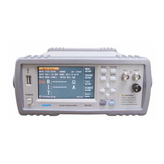
Introduction to Front and Rear Panels This chapter will describe the basic operation of SME1202A. Before using the instrument, please read this chapter carefully. Introduction to Front Panel Figure 2-1 shows the front panel of SME1202A. Figure 2-1 Front Panel... -
Page 11: Introduction To Rear Panel
This terminal connects the instrument chassis thus to protect or shield ground connection. HANDLER Interface Through HANDLER interface, an automatic test system can be conveniently constructed to realize auto test. SME1202A will output sorting comparator result signals and link signals. Meantime, “START” signal can be obtained through this interface. USB Interface PC can remotely control SME1202A through USB DEVICE. -
Page 12: Display Zone
Display Zone SME1202A adopts 24-bit 4.3-inch LCD touch screen with a resolution of 480*272. The display screen is divided into the following zones, as shown in figure 2-3. BIN1 Figure 2-3 Display zone Page name This zone shows the current page name. -
Page 13: Introduction To Buttons On Front Panel
Simple Operation Simple operation steps for SME1202A: Use [MEAS], [SYSTEM] or [FILE] or soft keys to enter into the page. (Refer to fig 2-5) Use arrow buttons ([←] [↑] [→] [↓]) to move the cursor to desired zone. - Page 14 BIN1 Figure 2-5 SME1202A Main Display SME1202A...
-
Page 15: Basic Operation
NOTE: Be sure to press STOP Save to end saving after START Save. Otherwise, the data may be lost. The following test condition information will be displayed in measurement/condition display zone on this page. These conditions (except the measurement internal resistance) can be set on < MEAS SETUP> page. MEAS STEP. SME1202A... -
Page 16: Measurement Functions
RANGE. OUTP VOLT. MONI VOLT. MEAS MODE. INTER RES. 3.1.1 Measurement Functions Measurable parameters on SME1202A are as follows: Primary Parameters R (Insulation resistance) I (Leakage current) Secondary Parameter T (Time count value of each procedure) The measurement results of primary parameters and secondary parameter are respectively displayed in three lines in the form of large characters. -
Page 17: Outp Volt
It is used for setting the measurement mode of the instrument as SINGLE. CONTI It is used for setting the measurement mode of the instrument as CONTI (continuous). Touch the corresponding key in soft key zone to select the relevant function. SME1202A... -
Page 18: Char Time
Touch the corresponding zone. The following items will be displayed in the soft key zone. AUTO It is used for setting the range selection mode as AUTO. LOCK It is used for setting the range selection mode as LOCK. Touch the corresponding key in soft key zone to select the relevant function. SME1202A... -
Page 19: Lock Range
This function is used for setting the contact check of the instrument. As the unique contact check function of SME1202A, this function can well identify the contact performance of components for capacitance, cable and other capacitive materials and reduce the occurring of error test. -
Page 20: Open Clr
1. When the MEAS TIME is set as 0s (i.e. this procedure is set as OFF), the Average times can be set as 1-999. 2. When the MEAS TIME is not set as 0s (i.e. this procedure is set as ON), the set SME1202A... -
Page 21: Meas Disp
Touch the soft key PICKOUT SETUP to enter into the <PICKOUT SETUP> page as shown in figure 3-3. Figure 3-3 PICKOUT SETUP The comparator functions of the instrument can be set on this page. SME1202A can set three groups of limit values for primary parameters. SME1202A... -
Page 22: Pick Func
Touch the corresponding zone. The following items will be displayed in the soft key zone. BIN ONE It is used to set buzzer alarm when the test value passes BIN ONE. BIN TWO It is used to set buzzer alarm when the test value passes BIN TWO. SME1202A... -
Page 23: Bin Disp
2. When the PICK LIVA is set as ON, whether the PICK ITEM is set as RESIS or CURR, set the limit value according to the above steps. 3. Whether the PICK LIVA is set as ON or OFF, the priority level of BIN1, BIN2 and BIN3 keeps invariant. SME1202A... -
Page 24: Outp Resu
Touching this key decreases the pulse width (set value) rapidly by 5. Start Test 3.4.1 Test Method Please connect the DUT (especially the DUT with polarity, such as the capacitor) according to the method as shown in figure 3-4 before testing. SME1202A... -
Page 25: Operation Process
DICH mark will blink when discharging. In addition, the three steps of charging, waiting and testing (when the DICH TIME is set as 0s, only press the DISCH key, the system changes from test status to discharge status) can be set as ON or OFF. SME1202A... -
Page 26: Range Selection
3.4.3 Range Selection There are six ranges of internal resistance in SME1202A. (refer to figure 3-1 below). Range Input Internal Resistance 1(1mA) 2(100µA) 3(10µA) 100k 4(1µA) 5(100nA) 6(10nA) 100M Figure 3-1 Range resistances When the RANGE SET of the instrument is set as AUTO, for different resistances being measured, the instrument will choose the optimal input resistance to achieve ideal measurement results. -
Page 27: System Setup And File Manage
LOCK SYSTEM Touch this key to enable the password function. Please input the password which will be required to be input when opening a file or starting up the instrument. SME1202A... -
Page 28: Bus Mode
Touch KEYSOUND, the following soft key zone will be displayed: Touch this key to turn on the key sound of touch screen. Touch this key to turn off the key sound of touch screen. You can touch soft key zone to set corresponding functions. SME1202A... -
Page 29: Triger
10-11-12 09:13:25. Operations are as follows: Touch the time zone to be modified, the following items will be displayed. ↑↑( ( ( ( + +) ) ) ) Touch this key and the value will increase rapidly by 5. SME1202A... -
Page 30: File Setup
Touch this key and the value will decrease rapidly by 5. <File Setup> SME1202A series can save parameters that are set by user to the internal non-volatile memory in the file format. User can load the file to use these parameters instead of resetting. - Page 31 U disk. If the U disk memory exceeds 512M, it is recommended to use FAT32 standard to format the disk. 3. Before a U disk is connected to SME1202A, you are recommended to save the data on it and we will not be liable for the data loss.
- Page 32 Touch this key, if the file name that the cursor locates is not empty, [YES] and [NO] will be displayed in the soft key zone. When [YES] is selected, the instrument will load the setup data in the file; when [NO] is selected, the current operation will be cancelled. SME1202A...
- Page 33 Touch “Copy to E”. The instrument will copy the selected file to a U disk. Select Touch “Select”, the tick mark √ will appear on selected file. SME1202A can simultaneously copy several selected files to a U disk. Touch “Select” once again, the selected file will be cancelled from selection.
-
Page 34: Performance Index
FAST SLOW Parameter Meas/sec ≤ 30ms Meas/sec ≤ 60ms Meas/sec ≤ 30ms Meas/sec ≤ 60ms 5.1.6 Display Digits Item Resistance 4-digit significant figures Range 1:100nA Range 2:10nA Leakage Range 3:1nA current Range 4:100pA Range 5:10pA Range 6:1pA Time 0.1s SME1202A... -
Page 35: Test Signal
Test Signal 5.2.1 Output Voltage Range Max. output DC Voltage range of SME1202A test terminal: 1 – 1000V. 5.2.2 Output Voltage Accuracy Voltage ≥ 10V: 1% ± 1V Voltage < 10V: 10% ± 0.1V 5.2.3 Maximum Display Range Parameter Measurement Display Range Resistance test 100.0k - 10.00T... -
Page 36: Remote Control
This standard is issued by EIA in 1969, which rules to send one bit in a data line every time. As most serial interfaces, the serial interface of SME1202A is also not strictly based on RS-232 standard but only uses the smallest subset of this standard. The signals are listed in the following table. -
Page 37: Scpi
Connect USB interfaces on PC and SME1202A through a USB cable. Install the Driver 6.3.2 When SME1202A is first connected to a PC through a USB cable, the prompt information –Found New Hardware will display on the right bottom of the computer desktop, as is shown below:... - Page 38 Click “NEXT”, dialogue 6-4 will pop up. Choose “Install the software automatically (recommended)”. Figure 6-4 Procedure 2 of Installing USB Driver When the installation of driver is finished, user can see “usb test and measurement device” in the device manager of PC, as is shown in the following figure. SME1202A...
-
Page 39: Usbvcom Virtual Serial Port
When “USBVCOM” is selected, the USB interface can be configured as a virtual serial port (VCom). System Configuration 6.4.1 Connect PC and SME1202A to the USB interface through a USB cable. Installing Driver 6.4.2 Methods of installing USBCDC driver are the same with that of installing USBTMC driver. - Page 40 Figure 6-6 VCom Display of PC Device Manager Now, usb VCom port acts as a serial port. When PC has no serial port, the communication software based on this serial port can be used as USB virtual serial port. SME1202A...
-
Page 41: Scip Command Reference
1. Data Conventions of This Manual NR1 :integer, for example:123 NR2 :fixed number, for example: 12.3 NR3 :floating number, for example: 12.3E+5 NL :CR character,integer: 10 ^END:EOI (end) signal of IEEE-488 bus. SME1202A Subsystem Commands ●DISPlay ●TRIGger ●COMParator ●DISCharge ●SYSTem ●FUNCtion ●FETCh? -
Page 42: Function Subsystem Commands
At this time, the zero base used in the measurenment is the factory default. Command syntax: FUNCtion: CZERo ON(1) OFF(0) Where, Character 1 (integer:49) means ON. Character 0 (integer: 48) means OFF. For example: WrtCmd(“:FUNC:CZER:ON”); Execute open zero clearing of the instrument. SME1202A... - Page 43 The : MSPeed command sets the measurement speed of the instrument. The :FUNCtion:MSPeed? query returns to the measurement speed of the instrument. FAST Command Syntax:FUNCtion: MSPeed SLOW Where, FAST and SLOW are respectively indicate fast and slow measurement. SME1202A...
- Page 44 The FUNCtion:WTIMe? query returns to the current wait time of the instrument. Command syntax: FUNCtion: WTIMe <value> Where, <value> is any real value among the wait time range (0-999.0s) of the instrument (correct to 0.1s). For example: WrtCmd(“FUNCtion:WTIme 12.5”); set the wait time of the instrument as 12.5s. SME1202A...
- Page 45 The :RANGe command sets the range of the instrument. The FUNCtion:RANGe? query returns to the current range parameters . Command syntax: FUNCtion: RANGe <value> Where, <value> can be 1mA、100uA、10uA、1uA、100nA、10nA For example: WrtCmd(“FUNC:RANG 1mA”); Set the range of the instrument as 1mA. SME1202A...
-
Page 46: Discharge Subsystem Commands
Query syntax: FUNCtion:MDISplay? Return format: <NL^END> 7.1.3 DISCharge Subsystem Commands DISCharge [:GO] Set the instrument to discharge. 7.1.4 TRIGger Subsystem Commands The TRIGger subsystem commands set the instrument trigger source and the delay time after triggering, and triggers instrument measurement. SME1202A... -
Page 47: Fetch? Subsystem Commands
7.1.5 FETCH? Subsystem Commands The FETCh? Subsystem commands are used to get the measurement result of SME1202A. Command Tree: FETCh [:IMP]? :AUTO ON(1) OFF(0) :SMONitor :VAC? :IAC? The [:IMP]? query returns SME1202A’s last measurement result to its output buffer. Query syntax: FETCh[:IMP]? SME1202A... - Page 48 Data format: <insulation resistance>, <leakage current>, <ultralimit> Ultralimit: downlap between the range onlap AUTO command makes SME1202A to send each measurement result to its output buffer automatically. Command syntax:FETCh:AUTO For example: WrtCmd(“FETC:AUTO ON”); The SMONitor command querys the monitor voltage.
-
Page 49: Comparator Subsystem Commands
Character 0 (integer: 48) means OFF. For example: WrtCmd(“COMP:FUNC ON”) Query syntax: COMParator:FUNCtion ? Return format: <NR1><NL^END> The :ITEM command sets the pickout item of the instrument. COMParator:ITEM? Query returns to the current pickout item. Command syntax: CURRent COMParator:ITEM RESistance SME1202A... - Page 50 BIN2 COMParator:BEEPer BTHRee it beeps when the beeper passes BIN3 COMParator:BEEPer it beeps when three bins of the beeper all failed COMParator:BEEPer turn off the beeper function Query Syntax: COMParator:BEEPer? Return format: BONe, BTWo, BTHRee, NG, OFF SME1202A...
- Page 51 COMParator:ORESult? query returns to the current bin output results type. Command syntax: LEVel COMParator:ORESult PULSe Where, LEVel set the bin output results type as LEVel PULSe set the bin output results type as PULSe For example: WrtCmd(“COMP:ORES LEV”) Query syntax: COMParator:ORES? Return format: LEVel <NL^END> PULSe SME1202A...
-
Page 52: System Subsystem Commands
The SYSTem:HPOWer INTernal or EXTernalcommands are used to set the Handler interface power. Command syntax: SYSTem:HPOWer INTernal set the HANDler power as INTernal. Query Syntax: SYSTem:HPOWer? Return format: INTernal (indicating the current HANDler power is INTernal), EXTernal (indicating the current HANDler power is EXTernal). SME1202A... -
Page 53: Mass Memory Subsystem Commands
Command syntax: *TRG For example: WrtCmd(“*TRG”); NOTE: ”*trg” will be valid when :INIT:CONT ON and trig:sour bus commands are enabled. The *IDN? query returns SME1202A’s identification string. Query syntax: *IDN? Return format: <manufacturer>,<model>,<firmware><NL^END> Where, <manufacturer> Name of Manufacturer <model>... - Page 54 Handler Interface SME1202A Insulation Resistance Meter equips with a Handler interface which is mainly used to output the sorting result. When the instrument is applied to an automatic component sorting test system, this interface will output the handshake signal and the sorting result output signal.
- Page 55 The pull-up resistors can be connected to the internally supplied voltage (+5V), or to an externally applied voltage (EXV: +5V) by setting through the setup item on the MEAS SETUP page. Comparator result output circuit and external control signal input circuit are shown as follows: SME1202A...
- Page 56 VCC_IO: Handler VCC, setting the HANDLER VCC as INTER or EXTER GND_IO: Handler GND, setting the HANDLER GND as INTER or EXTER SME1202A...
- Page 57 Warranty Conditions Scientific warrants all its Instruments to be free from defects in material and workmanship when used under normal operating conditions in accordance with the instructions given in the manual for a period of 12 (Twelve) months from date of purchase from Scientific or its authorized dealers.
- Page 58 Your Scientific instrument is a complex electronic device and deserves the best service available by technicians thoroughly familiar with its service and calibration procedures.
Need help?
Do you have a question about the SME1202A and is the answer not in the manual?
Questions and answers