Table of Contents
Advertisement
Quick Links
Advertisement
Table of Contents

Related Manuals for Scientific SM6024


Summary of Contents for Scientific SM6024
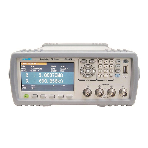
- Page 1 Precision LCR Meter SM6024 User Manual...
- Page 2 Information in this manual supercede all corresponding previous released material. Scientific continues to improve products and reserves rights to amend part or all of the specifications, procedures, equipment at any time without notice.
-
Page 3: Table Of Contents
LCR Meter SM6024 Table of Contents Introduction ........................6 1.1 Technical Specifications ....................7 1.2 First time operation......................9 1.3 Power connection ......................9 1.4 Fuse..........................9 1.5 Environment........................9 1.6 Use of Test Fixture ......................9 1.7 Warm-up ..........................10 Panel Controls .........................11 2.1 Front panel Controls ......................11 2.2 Rear panel Controls......................12... - Page 4 5.1.2 Point-frequency correction ..................49 5.2 Correct connection of DUT ....................50 5.3 Eliminate the influence of stray impedance..............51 5.4 Operation example for testing inductance with SM6024 ..........52 5.5 Operation example of testing capacitance by multi-frequency list sweep ....53 5.6 Setup example of comparator ..................54 5.6.1 Capacitor sorting ....................54...
- Page 5 6.4.8 Accuracy of L ......................66 6.4.9 Accuracy of Z ......................66 6.4.10 Accuracy of DCR ....................67 Command Reference .....................68 7.1 Subsystem commands for SM6024 ................68 7.1.1 MEASlay subsystem commands ................68 7.1.2 FREQuency subsystem commands...............70 7.1.3 VOLTage subsystem commands................70 7.1.4 CURRent subsystem commands .................71...
-
Page 6: Introduction
1. Introduction :LCR Meter SM6024 Basic accuracy: 0.05% 6 digit resolution Maximum test frequency of 200kHz Maximum test speed: 13 ms/time Automatic level control (ALC) function for V and I Test signal level monitor function for V and I Built in DC bias source... -
Page 7: Technical Specifications
Resolution Voltage accuracy 1% x set voltage + 5 mV Measuring time (> 10 kHz) Fast : 75meas/sec(13 ms), Medium : 11meas/sec(90ms) Slow : 2.7meas/sec(370ms) Average Times 1 – 255 Delay Time 0 – 60.000s, 1ms step User Manual SM6024... - Page 8 RS232C, RS485(option), LAN, USB Host, GPIB (optional), 0° C - 40° C, ≤90% RH Operating conditions Supply 230V ± 10% , 50Hz AC Power Consumption Max. 80 VA Dimensions (WxHxD) 215x88x335 mm Weight Approx. 3.6kg (Subject to change without notice) User Manual SM6024...
-
Page 9: First Time Operation
DUT, thus to guarantee the good connection between DUT and fixture. Connect the fixture or cable to four test terminals Hcur, Hpot, Lcur, Lpot on the front panel. As for the DUT with shielding shell, connect shielding layer or ground “┴”. User Manual SM6024... -
Page 10: Warm-Up
Note: When test fixture or cable has not being installed, the instrument will display an unstable test result. Warm-up 1) To guarantee the accurate measurement, the warm-up time is no less than 15min. 2) Please not turn on or off instrument frequently, in order to avoid the inner data fluster. User Manual SM6024... -
Page 11: Panel Controls
DC bias output is prohibited. The key is useless in some pages where the DC BIAS cannot be added. When the FUNC is set as DCR, Lp-Rd, Ls-Rd, this function is invalid. User Manual SM6024... -
Page 12: Rear Panel Controls
The function definition varies with different pages. 15) POWER Power switch Rear Panel Controls Figure 2-2 shows the rear panel of SM6024. Figure 2-2 Rear panel 1) IEEE-488 (GPIB) interface (Optional) The tester can communicate with PC through GPIB interface. -
Page 13: Display Zone
8) Serial Number Information about production serial number Display zone SM6024 has a 65k, 4.3-inch TFT display. The display screen is divided into the following zones: Figure 2-3 display zones 1) Display page name Indicate the name of the currently displayed page. -
Page 14: Main Menu Keys And Corresponding Displayed Pages
<FILE MANAGE> <SYSTEM SETUP> <TOOLS> MORE ► 2.4.3 [SYSTEM SETUP] This key-[SYSTEM SETUP] is used to enter into the system setup page. The following soft keys will be available: <SYSTEM SETUP> <MEAS SETUP> <DEFAULT SETTING> <SYSTEM RESET> User Manual SM6024... -
Page 15: Basic Operation
Basic Operation Basic operation of SM6024 is as follows: Use menu keys ([MEAS], [SETUP]) and soft keys to select the desired page. Use cursor keys ([←][→] [↑] [↓]) to move the cursor to the desired zone. When the cursor moves to a specified zone, the zone will become reverse expression. -
Page 16: Measurement Control
Signal source voltage/ current monitor (Vm, Im) Open, short, load correction ON/OFF status (CORR) 3.1.1 Test function In a measurement period, SM6024 can test two parameters for an impedance component: one primary parameter and one secondary parameter. Parameters that can be tested are as follows:... - Page 17 3) Press Cs—…→, the following parameters will be shown for your choice. Cs-D Cs-Q Cs-Rs RETURN← Press the soft key corresponding to your desired parameter. Then press RETURN ← to return to upper soft key menu. User Manual SM6024...
- Page 18 7) Press MORE→, the following parameters will be shown for your choice. Z—…→ Y—…→ R—…→ MORE→ 8) Press Z—…→, the following parameters will be shown for your choice. RETURN← Press the soft key corresponding to your desired parameter. Then press RETURN← to return to upper soft key menu. User Manual SM6024...
-
Page 19: Test Range
Measurement range should be selected in accordance with the impedance value of the tested LCR component. SM6024 has 11 AC measurement ranges: 1 , 3 , 10 , 30 , 100 , 300 , 1k , 3k , 10k , 30k , 100k . -
Page 20: Test Level
Refer to <MEASURE SETUP> for more information. Operation steps for setting test level: SM6024 provides two methods to set the level of test signal source. The first one is to use soft keys, while the second one is to input data by numeric keys. -
Page 21: Dc Bias
DCR, the BIAS zone will display “---”. Operation steps for setting DC bias: SM6024 provides two methods to set the DC bias. The first one is to use soft keys, while the second one is to input data by numeric keys. -
Page 22: Tools
3.1.7 Tools The test result of SM6024 is displayed as 6 floating-point digits. Decimal point lock function can make SM6024 output the test result in fixed way. Meanwhile this function can change the displayed count of test result. Operation steps for tools Set the display mode of decimal point in fixed mode according to the following operation steps. -
Page 23: Comparator Function
ON/OFF set state of OPEN, SHORT, LOAD (CORR) 3.2.1 Comparator function SM6024 has an inserted compare function which can divide DUT to up to 10 bins (from BIN1 to BIN9 and BIN OUT). Users can set 9 pairs of primary parameter limit and one pair of secondary bin limit. -
Page 24: Param
3) Press the soft key OFF to turn off the count function. 4) Press the soft key RESET COUNT, “☺ : Reset count, Sure?” will be displayed in the help zone. Then the following soft keys will be displayed. User Manual SM6024... -
Page 25: List Sweep Disp
<LIST SWEEP SETUP>. 3.4.1 Sweep mode The list sweep function of SM6024 can make automatic sweep test for up to 10 points’ test frequencies, test levels or DC bias. Two sweep modes are available on SM6024: SEQ and STEP. -
Page 26: Freq (Hz)
Test speed (SPEED) Trigger Mode (TRIG) Auto Level Control (ALC) Output Resistance (Rsou.) Average times (AVG) Voltage/Current Level Monitor ON/ OFF (Vm/Im) DCR polarity (DCR POL) Trigger delay (TRIG DLY) Step delay (STEP DLY) DC range (DC RNG) User Manual SM6024... -
Page 27: Trigger Mode
When the trigger mode is set as BUS, once the IEEE 488 interface receives a TRIGGER command, SM6024 will execute a test. The BUS mode cannot be set on the front panel. Note: In the process of testing, when SM6024 receives a trigger signal, it will be ignored. -
Page 28: Output Impedance
3) Press OFF to turn off the auto level control function. 3.5.3 Output impedance SM6024 provides two output impedances for your choice: 100 and 30 . When testing inductance, it is necessary to input the same output impedance so as to make data comparison with other instruments. -
Page 29: Dcr Polarity
OFF. 3.5.6 DCR polarity SM6024 can provide two DC resistance test mode: ALT and FIX. At present, only ALT mode can be used. ALT mode is positive and negative DC voltage measurement. FIX is to fix positive voltage measurement. ALT mode is conductive to the demagnetization when measuring the DC resistance of inductors, which makes the test more accurate. -
Page 30: Dc Level
MEASURE When the reference component is connected with the test terminal, you should press MEASURE. Then SM6024 will test the reference component and the test result will be automatically input as the value of REF A. 2) Use MEASURE or numeric keys to input the reference value of primary parameter. -
Page 31: Deviation Test Function
SM6024 provides two correction modes: the first one is executing open and short correction on all frequency points through interpolation method; the other one is executing open, short and load correction on the frequency point currently set. There are 201 calibration spots. The following measurement control parameters can be set on the <CORRECTION>... -
Page 32: Correction
Under the multiple correction mode, display the current channel number (CH NO.) 3.6.1 OPEN The open correction function of SM6024 can eliminate the error caused by the stray admittance (G, B) parallel-connected with DUT, shown as figure below. Stray Admittance... -
Page 33: Short
4) Press DCR OPEN, SM6024 will test the open-circuit resistance under the DC resistance function. 5) Press ON to turn on the function of open-circuit correction, then SM6024 will perform open-circuit correction calculation in the later testing process. If FREQ is set as OFF, the open-circuit correction data of the current frequency will be calculated by interpolation method. -
Page 34: Load
3) Press the MEAS SHORT soft key, SM6024 will test the short spurious impedances (resistance and reactance) of 34 frequencies. Short full frequency correction takes about 50 seconds and in this process, the following soft keys will be displayed. ABORT This soft key can be used to cancel the current short correction operation and reserve the formal open correction data. -
Page 35: Load Correction Test Function
Load correction function adopts the transport coefficient between the real test value of preset frequency and the standard reference value to eliminate the test error. Load correction function is only available for calculating transport coefficient. 3.6.5 Cable length selection The available cable length is 0m. User Manual SM6024... -
Page 36: Limit Table
Press [SETUP] and then LIMIT TABLE to enter into the <LIMIT TABLE SETUP> page as the following figure shown. Compare function can be set on this page. SM6024 can set 9 bin limits of primary parameters and one of secondary parameters. The tested result can be divided into up to 10 bins (BIN 1 to BIN 9 and BIN OUT). -
Page 37: Limit Modes Of Compare Function
3.7.3 Set nominal value of tolerance mode When the tolerance mode is selected as the limit mode of the primary parameter, it is necessary to set the nominal value. The nominal value can be any one within the display User Manual SM6024... -
Page 38: Comparator Function On/Off
3.7.4 Comparator function ON/OFF SM6024 can set 9 bin limits of primary parameters and 1 bin limit of secondary parameters. The tested results can be sorted into 10 bins (BIN 1 to BIN 9 and BIN OUT) at most. -
Page 39: High/Low
2) Use above soft keys to set the auxiliary function as ON or OFF. 3.7.6 HIGH/LOW SM6024 can set bin limits of 9 primary parameters and one secondary parameter. The test results can be sorted into 10 bins at most (BIN 1 to BIN 9 and BIN OUT). The high/low limits of primary parameters can be set in high limit and low limit of bins from BIN 1 to BIN 9. -
Page 40: Mode
The list sweep function of SM6024 can perform auto sweep test for the test frequency, test level or bias voltage of 10 points. On <LIST SWEEP SETUP> page, the following list sweep parameters can be set. Sweep mode (MODE) Sweep parameter setup (frequency [Hz], level [V], level [I], bias [V], bias [I]) -
Page 41: Tools
“---”. TOOLS Press [SETUP] and press TOOLS to enter into the <TOOLS> page shown as below. The TOOLS interface of SM6024 provides several specific functions and some custom design functions. CLEAR CORR 3.9.1 CORR DATA... -
Page 42: System] And
This soft key is used to select two low and short beeps. This soft key is used to set the pass beep function OFF. 4.1.3 FAIL BEEP This zone is used to control and display the beep mode as FAIL BEEP when the test result is unqualified. User Manual SM6024... -
Page 43: Language
Note: The default password is 0147852. 4.1.6 BUS MODE This mode is used to select RS232C, GPIB, USBTMC or USBCDC. Operation steps for setting bus mode Move the cursor to BUS, the following soft keys will be displayed. User Manual SM6024... -
Page 44: Gpib Addr (Reserved Function)
Operation steps for setting the baud rate Move the cursor to BAUD RATE, the following soft keys will be displayed. ↑(+) This soft key is used to increase the baud rate. ↓(-) This soft key is used to decrease the baud rate. User Manual SM6024... -
Page 45: Menu Disp
4.1.11 MENU DISP The soft key area of SM6024 series can be set as HOLD or fixed time. When MENU DISP is set to HOLD, the soft key area will be displayed all the time. When MENU DISP is set to fixed time, the soft key area will be auto hided after holding to the setting time. -
Page 46: U-Disk Manage Performance
5) Page format currently displayed 4.2.2 U-disk manage performance As described above, SM6024 has a standard configuration of USB HOST interface, so the external U-disk can be used as the memory media. In this condition, it breaks the memory limit of 40 groups of *.LCR files. Meanwhile those files can be copied to IBM PC or compatible desk-top computer, laptop with USB interface to reach the infinite extension. - Page 47 C. Load the control and setting parameters from a file by the following steps Press FILE MANAGE, the file list and the following soft keys will be displayed. LOAD STORE FIND COPY TO E: EXT. FILE User Manual SM6024...
- Page 48 3) Press LOAD, the following soft keys will be displayed. 4) Press No to cancel the current load operation and return step 1. 5) Press Yes to load the currently selected file. Then SM6024 will return the current display page.
-
Page 49: Execute Lcr Operation And Some Examples
Press kHz, the FREQ zone will be changed as 5.00000kHz (be the same as that of test frequency). k) Keep the test fixture be in open status and press MEAS OPEN to execute open correction. User Manual SM6024... -
Page 50: Correct Connection Of Dut
“+”, “Hc” or “Hp” and the low terminal should be connected to the terminal with mark “-”, “Lc” or “Lp”. Warning: Before testing, please discharge the tested polarity component so as to avoid the damage to the instrument. User Manual SM6024... -
Page 51: Eliminate The Influence Of Stray Impedance
By this way, the magnetic fields produced by these currents can be mutually offset and further eliminate the influence of mutual inductance coupling on test results. User Manual SM6024... -
Page 52: Operation Example For Testing Inductance With Sm6024
100 , 30 will be displayed in the soft key zone. k) Press 100 to select 100 as the signal internal impedance. 3) Connect the test fixture (26005) to the test terminals of SM6024. 4) Execute correction (To avoid the influence of stray impedance on measurement accuracy, Open/ Short correction must be operated) (refer to 5.1.2 “Point-frequency correction”) -
Page 53: Operation Example Of Testing Capacitance By Multi-Frequency List Sweep
Press [→] to move the cursor to the LMT zone of sweep point 2, this zone will be displayed as---. The following soft key will be displayed in the soft key zone: LIMIT DATA A, LIMIT DATA B and OFF. User Manual SM6024... -
Page 54: Setup Example Of Comparator
OFF. Refer to Correction operation in this chapter. Setup example of comparator SM6024 provides complete comparator function. It is convenient for component measurement and judgment, incoming and outgoing quality inspection in production line. Standard configuration of HANDLER interface makes it realize automatic sorting measurement system. -
Page 55: Operation Example Of Load Correction
4) Press SYSTEM key to enter into the SYSTEM SETUP page (System Config), find FAIL BEEP item and set it as HIGH LONG. 5) Return to the MEAS DISP page after setup. 5.6.2 Operation example of load correction 1) Operation steps Test condition Frequency: 100kHz Cp: 11nF D: 0.0005 User Manual SM6024... - Page 56 The load correction is only valid for the components with the same specification. If the specification is changed, it is required to redo load correction. User Manual SM6024...
-
Page 57: Performance And Test
6.1.5 Delay time Delay time: time from trigger to start. 0 to 60s are programmable with a resolution of 1ms. 6.1.6 Connection modes of test terminals SM6024 adopts 4-terminal test method. HD(Hcur): current sample high terminal LD(Lcur): Current sample low terminal HS(Hpot):voltage sample high terminal... -
Page 58: Test Speed (Frequency>=10Khz)
±(6%×preset value+ 10µA current 6.1.13 Output impedance 30 and 100 ±2% are selectable. 6.1.14 Monitor for test signal level Mode Range Accuracy Voltage —2V ±(3%×reading+0.5mV) 0.01mV —5mV ±(12%×reading +0.1mV) Current 50µA —20mA ±(3%×reading +5µA) 0.001µA —50µA ±(12%×reading +1µA) User Manual SM6024... -
Page 59: Maximum Measurement Display Range
The accuracy Ae of │Z│,│Y│,L,C,R,X,G and B are expressed as: )×100+ K = ±[A+(K ]×K A: basic test accuracy(figure A) :impedance rate factor(table A) :impedance rate factor(table A) :calibrated inter-factor(table B) :cable length factor(table D) :temperature factor(table E) User Manual SM6024... -
Page 60: Accuracy Of D
6.1.21 Accuracy of G When D (tested value of D)≤0.1 The accuracy of G is given by the formula below: ×D = 2πfC = —— πfL Where, B is the value of tested B with the unit [S]. User Manual SM6024... -
Page 61: Accuracy Of Rp
X with the unit [S]. is the value of test C with the unit [F]. is the value of test L with the unit [H]. is the accuracy of D F is test frequency User Manual SM6024... -
Page 62: Accuracy Factor
1. Obtain A according to the current measurement speed; 2. According to the current test signal voltage to select the accuracy modification coefficient (refer to figure B), the current basic measurement accuracy A is obtained by multiplying A got in step 1 with A User Manual SM6024... - Page 63 When the impedance is smaller than 500 , K is unavailable. When the impedance is larger than 500 , K is unavailable. Table B : calibrated interpolating factor K Test frequency Direct calibrated frequency Other frequency 0.0003 User Manual SM6024...
-
Page 64: Accuracy Of Dcr
6.2.2 Insulation intensity Under reference working condition, the insulation between the power terminal and the instrument jacket should bear an AC voltage (50Hz frequency and 1.5kV rated voltage) for 1 minute and there is no breakdown and flashover. User Manual SM6024... -
Page 65: Leakage Current
Adjust multimeter in AC voltage range, where one test cable is connected to H and the other is connected to ground terminal. Change level as: 10mV, 20mV, 100mV, 200mV, 1V, 2V, the reading should meet the demand of test signal level in this chapter. User Manual SM6024... -
Page 66: Frequency
H Change the frequency as: 20Hz, 100Hz, 1kHz, 10kHz, 100kHz CUR. (SM6024 is 100kHz). The reading of frequency meter should meet the demand of the test signal frequency in this chapter. 6.4.6 Measurement accuracy Basic parameters are R, L, C and D,so measurement accuracy is mainly about R, L, C and D. -
Page 67: Accuracy Of Dcr
Short correction should be made before testing. Connect standard DC resistors: 0.1 , 1 , 10 , 100 , 1k , 10k , 100k . The error between reading and nominal value should be in the range ruled in this section. User Manual SM6024... -
Page 68: Command Reference
The signs in this manual are as follows: NR1: integer, e.g.:123 NR2: fix-point number, e.g.: 12.3 NR3: floating-point number, e.g.: 12.3E+5 NL: carriage key, ASCII code: 10 ˆEND: EOI signal in IEEE-488 Subsystem commands for SM6024 DISPlay FREQuency VOLTage CURRent AMPLitude... - Page 69 The character string of the measurement item can be used as the file name when saving a file. Command syntax: MEASlay:LINE”<string>” Where, <string> can be an ASCII character string (maximum number is 16). For example: WrtCmd(“MEAS:LINE” Resistor meas””) Query syntax: MEASlay:LINE? Return format: <string><NL^END> User Manual SM6024...
-
Page 70: Frequency Subsystem Commands
NR1, NR2 or NR3 data format followed by Hz, kHz, MHz. Set the measurement frequency as 50Hz. Set the measurement frequency as 100kHz (The maximum frequency of SM6024 is 200kHz) For example: WrtCmd(“FREQ 1KHZ”) Set the frequency as 1000Hz. Query syntax: FREQuency? Return format: <NR3><NL^END>... -
Page 71: Current Subsystem Commands
Return format: <NR1><NL^END> 7.1.6 Output RESister subsystem commands The Output RESister subsystem commands are mainly used to set the output internal resistor mode. The Output RESister? query returns the current output internal resistance status. Command syntax: ORESister User Manual SM6024... -
Page 72: Output Subsystem Commands
7.1.8 BIAS subsystem commands The :BIAS subsystem commands are mainly used to set the internal bias voltage and the bias status. Command tree: BIAS :STATe ON (1) OFF (0) :VOLTage <value> (Only GPIB) :CURRent <value> User Manual SM6024... - Page 73 <value> NR1, NR2 or NR3 data format Set the bias current as 0A. Set the bias current as 10A. For example: WrtCmd (“BIAS:CURR MIN”) Set the DC bias current as 0A. Query syntax: BIAS:CURRent? Return format: <NR3><NL^END> User Manual SM6024...
-
Page 74: Function Subsystem Commands
±5V and the range of bias current is ±50mA.) 7.1.9 FUNCtion subsystem commands The FUNCtion subsystem commands are mainly used to set measurement functions, range, current/voltage monitor ON/OFF, deviation display mode, nominal setting. Command tree: User Manual SM6024... - Page 75 For example: WrtCmd (“FUNC:IMP:RANG 1KOHM”) Set the range as 1kOHM. Query syntax: FUNCtion:IMPedance:RANGe? Return format: <value><NL^END> Where, <value> can be 1000 3000 10000 30000 100000 • The FUNCtion:IMPedance:RANGe:AUTO command is used to set the automatic range selection status. The FUNCtion:IMPedance:RANGe:AUTO? query returns the current range status. User Manual SM6024...
- Page 76 The FUNCtion:DEV<n>:MODE? query returns the current deviation measurement mode. Command Syntax : ABSolute FUNCtion:DEV<n>:MODE PERCent Where, ABSolute Absolute value deviation display PERCent Percent deviation display Real Value display Where, <n> is Character 1 (49) is equal to the nominal value of primary parameter. User Manual SM6024...
- Page 77 <value> StepDELay Where, <value>NR1, NR2 or NR3 data format, 0-60s with the resolution of 1mS. Set the delay time as 0s. Set the delay time as 60s. For example: WrtCmd(“FUNC:SDEL 5S”) Set the delay time as 5s. User Manual SM6024...
-
Page 78: List Subsystem Commands
The LIST:VOLTage command is used to clear the original voltage of the each sweep point and reset the voltage. The LIST:VOLTage? query returns the current voltage of each sweep point. Command syntax: LIST:VOLTage<value>[,<value>*] NOTE: * part means 10 sweep points at most can be set. User Manual SM6024... - Page 79 NOTE: * part means 10 sweep points at most can be set. Where, <value> is NR1, NR2 or NR3 data format. For example: WrtCmd (“LIST:BIAS:VOLT 1.5V”) Set the DC bias voltage of sweep point 1 as 1.5V. Query syntax: LIST:BIAS:VOLTage? Return format: <NR3> [, <NR3>*] <NL^END> User Manual SM6024...
- Page 80 <low limit n> NR1, NR2 or NR3 data format, high limit of the sweep point on <high limit n> the n line. NR1, NR2 or NR3 data format, high limit of the sweep point on the n line. User Manual SM6024...
-
Page 81: Aperture Subsystem Commands
For example: WrtCmd (“APER MED, 55”) Query syntax: APERture? Return format: FAST <NR1><NL^END> SLOW 7.1.12 TRIGger subsystem commands The TRIGger subsystem commands are mainly used to set the instrument trigger source, trigger delay and trigger measurement. Command tree: User Manual SM6024... - Page 82 <value> In NR1, NR2 or NR3 data format, from 0 to 60s with 1ms as the resolution. MIN Set the delay time as 0s. MAX Set the delay time as 60s. For example: WrtCmd (“TRIG:DEL 5s”) Set the delay time as 5s. Query syntax: TRIGger:DELay? Return format: <NR3><NL^END> User Manual SM6024...
-
Page 83: Fetch? Subsystem Commands
The FETCh? subsystem commands are mainly used to direct SM6024 to input a measurement result. Command tree: The FETCh[:IMP]? query directs SM6024 to input the last measurement result to the output buffer zone. Query syntax: FETCh[:IMP]? For example: WrtCmd (“TRIG:SOUR BUS”) WrtCmd (“TRIG”) - Page 84 Result pass high When the compare function of the list sweep measurement is turned off, the output result of <Input/Output> is 0. <Input/Output> data output format applies 2-digits ASCII format: SN (S: +/_, N: from 0 to User Manual SM6024...
-
Page 85: Correction Subsystem Commands
7.1.14 CORRection subsystem commands The CORRection subsystem commands are mainly used to set the correction function, OPEN, SHORT, LOAD. Command tree: User Manual SM6024... - Page 86 <NL^END> MULTi • The CORReciton:OPEN command is used to execute open correction for 43 preset test points (SM6024 A has 41 preset test points). Command syntax: CORRection:OPEN For example: WrtCmd (“CORR:OPEN”) • The CORRection:OPEN:STATe command is used to set the open correction ON or OFF.
- Page 87 • The CORRection:SHORt command is used to execute short correction for 43 preset test points (SM6024 A has 41 preset test points). Command syntax: CORRection:SHORt For example: WrtCmd (“CORR:SHOR”) • The CORRection:SHORt:STATe command is used to set the short correction status.
- Page 88 0 (decimal 48) is equal to OFF. <n>: 1 refers to frequency spot 1. 2 refers to frequency spot 2. 3 refers to frequency spot 3. For example: WrtCmd (“CORR:SPOT1:STAT ON”) Query syntax: CORRection:SPTO<n>:STATe? Return format: <NR1><NL^END> User Manual SM6024...
- Page 89 3 refers to frequency spot 3. For example: WrtCmd (“CORR:SPOT1:FREQ 2KHZ”) Set the frequency of frequency spot 1 as 2KHZ. NOTE: <value> should be ranged from 20HZ to 300KHZ (SM6024 ), or return format will report errors. Query syntax: CORRection:SPOT<n>:FREQuency? Return format: <NR3><NL^END>...
- Page 90 <short 1/2/3 B> is NR3 data format and the secondary short correction data at frequency spot 1/2/3. <load1/2/3 A> is NR3 data format and the primary load correction data at frequency spot 1/2/3. <load1/2/3 B> is NR3 data format and the secondary load correction data at frequency spot 1/2/3. User Manual SM6024...
-
Page 91: Comparator Subsystem Commands
The COMParator[STATe]? query returns the current comparator state. Command syntax: COMParator[:STATe] Where, 1 (decimal 49) is equal to ON. 0 (decimal 48) is equal to OFF. For example: WrtCmd (“COMP ON”) Query syntax: COMParator[:STATe]? Return format: <NR1><NL^END>. User Manual SM6024... - Page 92 <high limit> is the high limit in NR1, NR2 or NR3 data format. NOTE: The low limit should be smaller than the high limit, or error information will be reported. For example: WrtCmd (“COMP:TOL:BIN1 -5,5”) WrtCmd (“COMP:TOL:BIN2 -10,10”) Query syntax: COMParator:TOLerance:BIN<n>? Return format: <low limit><high limit><NL^END> User Manual SM6024...
- Page 93 The COMParator:Auxiliary BIN? query returns the current auxiliary bin state. Command syntax: COMParator:Auxiliary BIN Where, 1 (decimal 49) is equal to ON. 0 (decimal 48) is equal to OFF. For example: WrtCmd (“COMP:ABIN ON”) Query syntax: COMParator:Auxiliary BIN? Return format: <NR1><NL^END> User Manual SM6024...
- Page 94 1 (decimal 49) is equal to ON. 0 (decimal 48) is equal to OFF. For example: WrtCmd (“COMP:BIN:COUN ON”) Query syntax: COMParator:BIN:COUNt[STATe]? Return format: <NR1><NL^END> • The COMParator:BIN:COUNt:DATA? query returns the current comparison result of the bin count. Query syntax: COMParator:BIN:COUNt:DATA? User Manual SM6024...
-
Page 95: Dcr Subsystem Commands
Query syntax: DCR:LEVEL? Return format: <NR3><NL^END> The DCR:POL command is used to set the DCR test mode. The command DCR:POL? query returns the test mode. Command syntax: DCR:LEVEL Where, <ALT> alternative test mode of positive and negative level User Manual SM6024... -
Page 96: Mass Memory Subsystem Commands
0 (decimal 48) is equal to OFF. For example: WrtCmd (“DCR:RANG:AUTO ON”); set the range auto to ON. Query syntax: DCR:RANG:AUTO? Return format: <NR1><NL^END> 7.1.17 Mass MEMory subsystem commands The Mass MEMory subsystem commands are used for file storing and load. Command tree: User Manual SM6024... -
Page 97: Gpib Common Commands
For example: WrtCmd (“*TRG”) The *CLS command clears the standard event status register and the service request status register. Command syntax: *CLS For example: WrtCmd (“*CLS”) The *IDN? query returns SM6024 ID. Query syntax: *IDN? User Manual SM6024... - Page 98 <firmware> Firmware Version For example: WrtCmd(“*IDN?”); The *TST? query executes an internal self test and returns the test result as the sum of all existing errors codes. If there are no error SM6024 returns 0. Query syntax: *TST? Return format: 0<NL^END> Where, 0(NR1 format)...
- Page 99 The execution of this command will not affect contents of the standard status byte register. Query syntax: *STB? Return format: <value><NL^END> Where, <value> NR1 format: decimal expression for contents of the standard status byte register. Descriptions for each bit of the standard status byte register User Manual SM6024...
- Page 100 For example: WrtCmd (“*STB?”) The *OPC command equals to set the OPC bit of the standard event status register when SM6024 finishes all parameter measurements. Ever since all pending operations have been completed, this command will inform the instrument to add a ASCII number “1”...
-
Page 101: The Description For Handler
8 The description for Handler (optional) The SM6024 provides the Handler interface for you. The interface is mainly used for the output of the sorted result. The interface offers the communication signal and the signal for the output of the sorted result. The separator result is corresponding to the output of BIN 10. - Page 102 /BIN9 /OUT /AUX /EXT.TRIG External trigger: when the trigger mode is EXT.TRIG, SM6024 will be triggered by the positive-edge pulse signal in this pin. EXT.DCV2 External DC voltage 2: The DC provider pin for the optoelectronic coupling signal (/EXT_TRIG, /KeyLock, /ALARM, /INDEX,...
- Page 103 End Of Measurement:when the test data and the compared result are effective, this signal is effective. 32,33 COM2 The reference ground for external power EXTV2. 34,35,36 COM1 The reference ground for external power EXTV1. Table 2 signal distribution for the pins User Manual SM6024...
- Page 104 User Manual SM6024...
- Page 105 /AUX shows PASS/FAIL judgment. When a sweep test is finished, these signals will be the output signal. Control output signal /INDEX (analog test finished), /EOM (the test ended). The timing is below when /INDEX and /EOM are effective: User Manual SM6024...
- Page 106 STEP: When the test of every sweep point is finished, /EOM is finished. the comparison result signal is effective until /EOM is effecive. others The definition is the same to that of the comparison. User Manual SM6024...
- Page 107 User Manual SM6024...
-
Page 108: Electrical Feature
The output voltage on every line is set by the pull-up resistance on the HANDLER interface board. The pull-up resistance is connected to the internal voltage (+5v), or the external voltage(EXTV:+5v). User Manual SM6024... -
Page 109: Handler Interface Board Circuit
/OUT /PHI /PLO ≤0.5V control +5V--+24V Internal pull-up signal voltage : /INDEX SM6024 GND /EOM EXTV2: /ALARM COM2 8.2.3 HANDLER Interface board circuit The output circuit for the comparison result is shown in the figure 6 below. User Manual SM6024... - Page 110 The output circuit for control signal is shown in the figure 7 below. User Manual SM6024...
- Page 111 The input circuit for control signal is shown in the figure 8 below. User Manual SM6024...
-
Page 112: Operation
(1) Set the range to the maximum that the capacitance may be, and lock this range. (2) Set Vm: OFF and Im: OFF in the MEAS SETUP page. (3) Test the DUT in the BIN COUNT page. User Manual SM6024... -
Page 113: Maintenance, Dispatch Procedure For Service &Warranty Conditions
12 (Twelve) months from date of purchase from Scientific or its authorized dealers. The service during the warranty period will be rendered on return to factory / service center basis.
Need help?
Do you have a question about the SM6024 and is the answer not in the manual?
Questions and answers