Table of Contents
Advertisement
Quick Links
Advertisement
Table of Contents

Subscribe to Our Youtube Channel
Related Manuals for Burkert 8750 REV.2


Summary of Contents for Burkert 8750 REV.2
- Page 1 Type 8750 REV.2 Flow controller Quickstart English...
- Page 2 We reserve the right to make technical changes without notice. Technische Änderungen vorbehalten. Sous réserve de modifications techniques. © Bürkert Werke GmbH & Co. KG, 2022 Operating Instructions 2212/00_EU-ML_00815443 / Original DE...
-
Page 3: Table Of Contents
Typ 8750 REV.2 Table of Contents ASSEMBLY ................20 QUICKSTART GUIDE ............5 9.1 Safety instructions ............. 20 1.1 Definition of terms / Abbreviation ........ 5 9.2 Before installation ............20 SYMBOLS ................5 9.3 Pneumatic connection of the process controller..20 AUTHORIZED USE ............... 6 10 ELECTRICAL INSTALLATION ..........22 BASIC SAFETY INSTRUCTIONS .......... - Page 4 Typ 8750 REV.2 16 ERROR MESSAGES ............38 16.1 Error messages on field bus devices ......40 16.2 Other error messages ..........40 17 ACCESSORIES ..............41 17.1 Communications software......... 41 18 DISASSEMBLY ..............42 19 OPERATING STRUCTURE ..........43 20 TRANSPORT, STORAGE, PACKAGING ......52 english...
-
Page 5: Quickstart Guide
Typ 8750 REV.2 Quickstart Guide QUICKSTART GUIDE SYMBOLS The quickstart guide contains the most important information and The following symbols are used in these instructions. notes regarding the use of the device. DANGER! Keep the quickstart guide in a location which is easily accessible to every user and make it available to every new owner of the device. Warns of an immediate danger. ▶ Failure to observe the warning will result in a fatal or serious injury. Important Safety Information. Read Quickstart carefully and thoroughly. Study in particular WARNING! the chapters entitled Basic Safety Instructions and Authorized Use. Warns of a potentially dangerous situation. ▶ Quickstart must be read and understood. ▶ Failure to observe the warning may result in a serious or fatal injury. -
Page 6: Authorized Use
Typ 8750 REV.2 Authorized use AUTHORIZED USE BASIC SAFETY INSTRUCTIONS These safety instructions do not make allowance for any Non-authorized use of the flow controller Type 8750 may be • Contingencies and events which may arise during the installation, a hazard to people, nearby equipment and the environment. operation, and maintenance of the devices. ▶ The device is designed as a simple system for determining and controlling the volumetric flow rate of gases. • Local safety regulations – the operator is responsible for observing ▶ Do not expose the device to direct sunlight. - Page 7 Typ 8750 REV.2 Basic safety instructions NOTE! General hazardous situations. ▶ Devices without a separate Ex type label may not be used in Electrostatic sensitive components/modules. a potentially explosive area. The device contains electronic components which react sen- ▶ Only trained technicians may perform installation and main- sitively to electrostatic discharge (ESD). Contact with electro- tenance work. statically charged persons or objects are hazardous to these ▶ Ensure that the system cannot be activated unintentionally. components. In the worst case scenario, they will be destroyed ▶ After an interruption in the power supply or pneumatic supply, immediately or will fail after start-up. ensure that the process is restarted in a defined or controlled ▶ Observe the requirements specified in EN 61340-5-1 to manner. minimize/avoid the possibility of damage caused by a sudden ▶...
-
Page 8: General Information
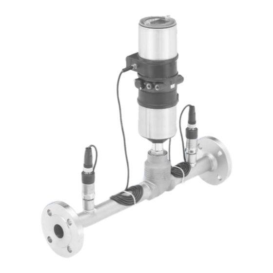
Typ 8750 REV.2 General information GENERAL INFORMATION SYSTEM DESCRIPTION Contact address General description Germany The fluid flow rate controller Type 8750 is a complete system for measuring and controlling the volume flow of gases according to the Bürkert Fluid Control Systems differential pressure principle. The system consists of an ELEMENT Christian-Bürkert-Str. 13-17 control valve Type 2301 with the process controller Type 8693 as D-74653 Ingelfingen well as two pressure sensors. It is supplied as a fully assembled E-mail: info@de.buerkert.com system including special housing. International Options: Contact addresses can be found on the final pages of the printed • Digital input operating instructions. • Analog feedback And also on the Internet at: • 2 digital outputs www.burkert.com • Bus communication (EtherNet/IP, PROFINET, PRO- FIBUS DPV1, Modbus TCP) Warranty The warranty is only valid if the flow controller Type 8750 is used as intended in accordance with the specified application conditions. -
Page 9: Structure
Typ 8750 REV.2 System description Structure 6.2.2 Influence of the process variables on the flow rate Process controller Type 8693 Pressure drop Flow rate of gases Actuator control subcritical Valve body control · ∆p valve Type 2301 valve Type 2301 = 514 · k > · p Signal line from Pressure sensor supercritical pressure sensor Type 8323 = 257 · k to the process <... - Page 10 Typ 8750 REV.2 System description 6.2.3 Electrical interfaces Inputs for (set-point value) 2 digital outputs position or Process controller process setpoint Inputs for Type 8693 value Analog process actual Process con- PROFIBUS DPV1 0...20 mA position value (4...20 mA) troller EtherNet/IP 4...20 mA feedback Type 8693 0...5 V PROFINET Modbus TCP 0...10 V Inputs for 24 V DC process actual value (4...20 mA) Operation Fig. 4:...
-
Page 11: Technical Data
Typ 8750 REV.2 Technical data TECHNICAL DATA Control cone Stainless steel 1.4571 Spindle Stainless steel 1.4404 (316L) Standards and directives Dowel pin Stainless steel 1.4310 The device complies with the relevant EU harmonisation legis- lation. In addition, the device also complies with the require- Inlet and outlet sections acc. to EN ISO 5167-1 ments of the laws of the United Kingdom. Inlet sections The harmonised standards that have been applied for the con- formity assessment procedure are listed in the current version of the EU Declaration of Conformity/UK Declaration of Conformity. Valve completely open Operating conditions Ambient temperature 0...+55 °C 20 x D Degree of protection: IP65 / IP67 according to EN 60529 (only if cables, plugs and sockets have been connected correctly 90° bend or T-piece... - Page 12 Typ 8750 REV.2 Technical data Dimensions Type ELEMENT Dimensions Type CLASSIC ∅ 91 ∅ 91 ∅ E ∅ E 2x DN 6x DN 2x DN 6x DN Fig. 6: Dimensions Type ELEMENT Fig. 7: Dimensions Type CLASSIC DN port con- Actuator ∅ E DN port con- Actuator size ∅...
-
Page 13: Type Label (Example)
Typ 8750 REV.2 Technical data Type label (example) Pressure range control medium ELEMENT 5.5...7 bar Nominal diameter Seat seal material CLASSIC 5...6 bar Control function Body material Medium air and gases Type Pilot pressure Ambient temperature 0...+55 °C 8750 A 50,0 PTFE VA Pilot 5,5- 7bar Temperature range media 0...+80 °C FLANSCH Pmed 16bar Made in Germany 00123456 Pressure range media 0...16 bar W12ME Flow 1 Pressure measurement 0...0.1 bar (overpressure) Order number Max. medium pressure range of sensor 0...0.16 bar (overpressure) Port connection 0...0.25 bar (overpressure) -
Page 14: Electrical Data
Typ 8750 REV.2 Technical data Electrical data 7.6.1 EtherNet/IP, PROFINET, Modbus TCP Connections Network speed 10/100 Mbps Operating voltage circular plug-in connector M12 x 1, Auto Negotiation 4-pin Switch function Internal system signals 2x circular plug-in connectors Network diagnostics Yes, via error frames M8 x 1, 4-pin MAC-ID Individual ID number, stored in the module and on the outside of the Input/output signal circular plug-in connector M12, device (refer to type label) 8-pin or bus connections Device name Ethernet Operating voltage 24 V DC (factory setting) XXX (name can be modified) maximum residual ripple 10 % Power consumption < 5 W Set-point value default 0/4...20 mA or 0...5/10 V... - Page 15 Typ 8750 REV.2 Technical data Valve variant Flow rate Kv in [%] Actuator Valve stroke POS [%] pipe seat size Ø Characteristic [mm] [mm] (theo. setting ratio) [m³/h] 03,0 linear (10:1) 7,0 10,0 15,0 20,0 25,0 31,0 37,0 44,5 52,0 58,0 65,0 71,5 78,0 84,0 90,0 95,0 100,0...
-
Page 16: Control And Display Elements
Typ 8750 REV.2 Control and display elements CONTROL AND DISPLAY ELEMENTS Function of the keys The functions of the 4 keys differ depending on the operating state (AUTOMATIC or MANUAL) and operating level (process level or Designation: setting level). Function of Display The function of the keys is displayed in the gray text field which is the keys above the key. MENU INPUT MANU MENU AUTO left right Function of the keys on the process level:... -
Page 17: Operating State
Typ 8750 REV.2 Control and display elements Operating state Function of the keys on the setting level: The process controller has 2 operating states: Function of the Description of the function AUTOMATIC and MANUAL keys Arrow key Scroll up in the menus AUTOMATIC In the AUTOMATIC operating state, Increase numerical values MENU normal controller mode is implemented. Arrow key Scroll down in the menus (Bar running along the upper edge of the MENU CMD POS MANU... -
Page 18: Operating Levels
Typ 8750 REV.2 Control and display elements Operating levels Display in AUTOMATIC operating state The process controller has 2 operating levels: set at the Description of the display Display • Process level factory D isplay and operation of the current process Operating state: AUTOMATIC / MANUAL Set-point position of the valve • Setting level actuator (0 – 100 %) MENU SP/PV CMD MANU I nputting the operating parameters... -
Page 19: Master Code
Typ 8750 REV.2 Control and display elements set at the set at the Description of the display Display Description of the display Display factory factory P.LIN Graphical display of SP and PV Automatic linearization of the – – with time axis process characteristics SP / PV (t) MENU HOLD MENU P.TUNE CMD/POS Simultaneous display of the Graphical display of POS and nominal position and the set- –... -
Page 20: Assembly
Typ 8750 REV.2 Assembly ASSEMBLY Before installation The FMR can be installed in any position, preferably with the Safety instructions process controller face up. DANGER! ▶ For trouble-free flow characteristics on the pressure sensor, fit an inlet section upstream of the FMR (dimen- Risk of injury from high pressure in the equipment/device. sions acc. to EN ISO 5167-1, see “Fig. 5: Inlet sections”, ▶ Before working on equipment or device, switch off the pressure page 11) and deaerate/drain lines. ▶ Ensure that the pipelines are correctly lined and are not twisted. If necessary, pipelines must be suitably Risk of electric shock. attached or supported. ▶ Before reaching into the device, switch off the power supply ▶ Observe flow direction (arrow on type label, 2 to 1). - Page 21 Typ 8750 REV.2 Assembly WARNING! Exhaust air port Risk of injury when opening the actuator. label: 3 The actuator contains a tensioned spring. If the actuator is opened, there is a risk of injury from the spring jumping out. ▶ The actuator must not be opened. Risk of injury from moving parts in the device. ▶ Do not reach into openings. Risk of injury from unsuitable connection hoses. Pilot air port Additional exhaust air port Hoses which cannot withstand the pressure and temperature Label: 3.1 label: 1 range may result in hazardous situations.
-
Page 22: Electrical Installation
Typ 8750 REV.2 Electrical installation ELECTRICAL INSTALLATION Procedure: → Connect the process controller according to the following tables. DANGER! When the operating voltage is applied, the process controller is operating. Risk of electric shock. ▶ Before reaching into the device, switch off the power supply → Now enter the required basic settings and actuate automatic and secure to prevent reactivation. adjustment of the process controller, as described in chapter “11 Start-up 24 V DC”, page 26. ▶ Observe applicable accident prevention and safety regulations for electrical equipment. Circular plug M18, 4-pin Pressure sensor P1, P2 WARNING! Risk of injury from improper installation. ▶ Installation must only be carried out by authorized technicians Circular plug M12, 4-pin and with the appropriate tools. -
Page 23: 10.2 Electrical Installation Profibus Dpv1
Typ 8750 REV.2 Electrical installation 10.2 Electrical installation PROFIBUS DPV1 Circular plug M12, 8-pin Set-point value, digital input Procedure: Wire color Assignment Set-point value + (0/4...20 mA / 0...5/10 V) → Connect the process controller according to the tables. blue Set-point value GND white Digital input + The electrical connection module of Type 8693 features a setscrew Input/output signals with nut which is used to connect the functional earth (FE). Wire color Assignment → Connect setscrew to a suitable grounding point. To ensure pink Analog position feedback + electromagnetic compatibility (EMC), ensure that the cable is gray Analog position feedback GND as short as possible (max. 30 cm, Ø 1.5 mm yellow Digital output 1 green Digital output 2... - Page 24 Typ 8750 REV.2 Electrical installation Socket M12, 5-pin (bus connection) Circular plug M8, 4-pin Signal Pressure sensor P1, P2 VP+5 RxD/TxD-N Circular plug M12, 5-pin DGND (inversely coded or RxD/TxD-N B coded) Shielding PROFIBUS DPV1 Tab. 11: Socket M12, 5-pin (bus connection) FE connection Socket M12, 5-pin Circular plug M8, 4-pin (pressure sensor) (inversely coded or Wire color Assignment B coded)
-
Page 25: Electrical Installation Ethernet/Ip, Profinet And Modbus Tcp
Typ 8750 REV.2 Electrical installation 10.3 Electrical installation EtherNet/IP, X7: Fieldbus connection M12 D, coded: PROFINET and Modbus TCP Pin 1 Transmit + Pin 2 Receive + Procedure: Pin 3 Transmit – → Connect the process controller according to the tables. Pin 4 Receive – The electrical connection module of Type 8693 features a setscrew Tab. 14: Elctrical assignment EtherNet/IP with nut which is used to connect the Functional earth (FE). Circular plug M8, 4-pin (pressure sensor) →... -
Page 26: Start-Up 24 V Dc
Typ 8750 REV.2 Start-up 24 V DC START-UP 24 V DC 11.1 General procedure for creating settings for the flow controller WARNING! Action Description Risk of injury from improper operation. Switching from MENU MENU Press for 3 s Improper operation may result in injuries as well as damage to process level setting level (countdown in the the device and the area around it. -
Page 27: Automatic Adjustment (X.tune)
Typ 8750 REV.2 Start-up 24 V DC 11.3 Automatic adjustment (X.TUNE) Change to INPUT menu ENTER MENU Press WARNING! Select 4...20 mA, Select the input signal 0...20 mA, 0...10 V or Danger of injury due to the valve position changing when the 0...5 V X.TUNE function is run at operating pressure. Specifying the input signal SELEC MENU ▶... -
Page 28: Configuring The F.control Auxiliary Function
Typ 8750 REV.2 Start-up 24 V DC 11.4 Configuring the F.CONTROL auxiliary Procedure: function Taste Action Description Switching from → Add the auxiliary function F.CONTROL to the main menu MENU MENU Press for 3 s process level setting level using the configuration menu (ADDFUNCTION). (countdown in the display) Procedure: Select X.TUNE Selection X.TUNE menu Action Start of the automatic MENU Press for 5 s adjustment X.TUNE MENU... - Page 29 Typ 8750 REV.2 Start-up 24 V DC F.CONTROL - Settings: F.CONTROL PID.PARAM DBND 1 % ENTER ENTER Parameter settings for the PID process PID.PARAM 1,00 controller Insensitivity area (dead band) of the PID 999,9 DBND 0,1 % process controller 0,00 Amplification factor of the process controller 0,0 % FILTER EXIT Reset time Hold-back time F.PARAM...
- Page 30 Typ 8750 REV.2 Start-up 24 V DC 11.4.1 Change the process set-point value Scaling the position controller SP-SCALE (for external set-point value default only) Procedure: Enables a smooth switchover between 1. Set the set-point value default on the setting level: P.CO-INIT AUTOMATIC and MANUAL operating state In the main menu (MAIN), select the F.CONTROL function Save a valve-specific Kv characteristic VALVE and the Kvs value, customer settings also intern ENTER ENTER SETUP SP-INPUT F.CONTROL possible SELEC PRESSURE Setting the measuring range of the pressure SENSOR sensors → Use the key (press 4 x) to return to the process level.
-
Page 31: Leakage Air Characteristic For Fmr (Leaktune)
Typ 8750 REV.2 Start-up 24 V DC 11.5 Leakage air characteristic for FMR NOTE! (LeakTune) If bulk material is conveyed pneumatically using a rotary The function LEAK.TUNE enables leakage air compensation valve, ensure that which increases the precision of the fluid flow rate control. ▶ the conveyor line behind the rotary valve is closed. Background: When bulk material is conveyed, leakage air occurs ▶ the rotary valve is empty and is running at nominal speed. on a rotary valve depending on the pressure. The air flow through ▶ Measures for sealing the system (e.g. sealing air which flows the controller unit is divided into this leakage air and into the air down into the rotary valve) are implemented. flow in the conveyor line. -
Page 32: Additional Fmr Functions
Typ 8750 REV.2 Additional FMR functions 11.5.2 Program sequence ADDITIONAL FMR FUNCTIONS • The control valve is closed. Overview • After 10 seconds settling time the primary pressure is recorded ADD.FUNCTION CHARACT on the fluid flow rate controller. ENTER CUTOFF The scaling of the x axis of the leakage air characteristic is DIR.CMD based on this pressure value. DIR.ACT The upper limit results in the factor 0.85. X.LIMIT Up to 21 support points are determined. X.TIME Example values: A primary pressure of 2.0 bar results in a characteristic of 0 to 1.7 bar in 85 mbar steps. X.CONTROL SECURITY • The control valve is slowly opened within a ramp time of 60 SAFEPOS seconds. SIG.ERROR •... -
Page 33: Activating And Deactivating Auxiliary Functions
Typ 8750 REV.2 Additional FMR functions No Description No Description Selecting the transfer characteristic between input signal Diagnosis menu (option) and stroke (correction characteristic) Parameterization of the PID process controller Sealing function for position controller Tab. 22: Description of auxiliary functions Effective sense of direction between input signal and The auxiliary functions listed here can be activated and set in nominal position accordance with the control task. Assignment of the aeration state of the actuator chamber to the set-point position A detailed description of the auxiliary functions and set- tings can be found in the user instructions for Type 8693 Limit the mechanical stroke range (see www.burkert.com). Limit the control speed The following auxiliary functions differ from Type 8693 and are Parameterization of the position controller described in these instructions: Code protection for settings • CAL.USER see Chapter “12.2 CAL.USER - Changing the factory calibration”... -
Page 34: Cal.user - Changing The Factory Calibration
Typ 8750 REV.2 Additional FMR functions 12.1.1 Including auxiliary functions in the main CAL.USER menu Procedure: calibr. POS ENTER Action POS. pMIN ENTER MENU MENU Press for approx. 3 s INPUT Select ADD.FUNCTION Enter value ENTER MENU Press (POS.lower:) Select the auxiliary function ENTER MENU POS. pMAX... - Page 35 Typ 8750 REV.2 Additional FMR functions CAL.USER - Settings: calibr. PV PV 4 mA 0 Create and ENTER calibr. POS Calibration of the position actual value confirm INPUT POS. pMIN Set the minimum position of the valve minimum value POS. pMAX Set the maximum position of the valve PV 20mA 0 EXIT Create and...
-
Page 36: Output - Configuration Of The Analog Output
Typ 8750 REV.2 Additional FMR functions OUT ANALOG SELEC calibr. PV Calibrating the process actual value Output of the actual value ENTER for input signal 4 - 20 mA: Output of the set-point value Output of the process actual value PV 4mA 0 Minimum value of the input signal Output of the process set-point value PV 20mA 0 Maximum value of the input signal Output of the pressure P1 (input) for input signal Pt 100: Output of the pressure P2 (output) Output of medium temperature MTMP 0000 Temperature copyFACT->USER Reset to factory settings... -
Page 37: Profibus Dpv1 Start-Up
Typ 8750 REV.2 PROFIBUS DPV1 start-up PROFIBUS DPV1 START-UP SAFETY END POSITIONS Procedure: Safety end positions after • Perform the automatic adjustment (X.TUNE) of the process Actuator failure of the auxiliary power Designation controller. system electrical pneumatic • Add the F.CONTROL auxiliary function to the main menu using the configuration menu (ADDFUNCTION) and make settings. -
Page 38: Error Messages
Typ 8750 REV.2 Error messages ERROR MESSAGES Error messages while the X.TUNE function is running General error messages (display only for external set-point value Display Cause Remedial action and with activated SIG.ERR). X.TUNE No compressed air Connect com- Display Cause Remedial action ERROR 1 connected. pressed air. Check com- Minimum input value has Do not reduce X.TUNE Compressed air failure while pressed air been reached. value further. ERROR 2 X.TUNE is running supply. Maximum input value has Do not increase X.TUNE Actuator or control system Not possible, been reached. - Page 39 Typ 8750 REV.2 Error messages Error messages while the P.Q‘LIN / P.TUNE function is running Error messages while the LEAK.TUNE function is running Display Cause Remedial action Display Cause Remedial action P.Q LIN No compressed air con- Connect com- P1 error No primary pressure on the Switch on com- nected. pressed air. controller unit. The primary pressor before ERROR 1 pressure is less than 50 starting to determine Check process and, mbar. the leakage air. No change to process if required, switch on variable. pump or open the P2 error...
-
Page 40: Error Messages On Field Bus Devices
Typ 8750 REV.2 Error messages 16.1 Error messages on field bus devices 16.2 Other error messages Display Cause Remedial action Display Cause Remedial action MFI fault Not pos- Field bus board Not possible, POS = 0 Sealing function Deactivate sible, device defective. device defective. (bei CMD > 0 %) or (CUTOFF) is unin- sealing function. defective. tentionally activated. POS = 100 %, (when CMD < 100 %). -
Page 41: Accessories
Typ 8750 REV.2 Accessories ACCESSORIES Wrench for opening/closing the trans- 674077 parent cap Designation Order no. Tab. 33: Accessories M12 connecting cable, 8-pin, 919267 5 m assembled cable 17.1 Communications software M12 connecting cable, 4-pin, 918038 5 m assembled cable The PC operating program “Bürkert Communicator” is designed for communication with devices from the Bürkert positioner family. M8 connecting cable, 4-pin 264602 5 m assembled cable M12 connecting cable, 4-pin, A detailed description and precise schedule of the pro- on request 5 m assembled cable, D coded cedure for the installation and operation of the software can be found in the associated documentation. -
Page 42: Disassembly
Typ 8750 REV.2 Disassembly DISASSEMBLY DANGER! Process Risk of injury from high pressure in the equipment/device. Electrical controller ▶ Before working on equipment or device, switch off the pressure connection and deaerate/drain lines. Risk of electric shock. ▶ Before reaching into the device, switch off the power supply Pneumatic connection and secure to prevent reactivation. ▶ Observe applicable accident prevention and safety regulations for electrical equipment. WARNING! Risk of injury from improper removal. -
Page 43: Operating Structure
Typ 8750 REV.2 Operating structure OPERATING STRUCTURE Baudrate 9.6 kBd The factory presets are highlighted in blue to the right of the 19.2kBd menu in the operating structure. 31.25 kBd Menu options activated or selected at the factory 45.45 kBd M enu options not activated or selected at the 93.75 kBd factory 187.5 kBd 2 %, 10 sec Values set at the factory 500 kBd 1.5 MBd ACTUATOR SINGLE 3 MBd DOUBLE 6 MBd 12 MBd... - Page 44 Typ 8750 REV.2 Operating structure M.TUNE.POS ACT.limit GRAPH FREE Graph ACT.nolimit Y0 -> 0 % Y5 -> 5 % M.TUNE.PWM yB.min CUTOFF yE.min M.TUNE.AIR 100 % Y100 -> 100 % P.Q‘LIN Starting process Type PCO CUT-type Type XCO P.TUNE Starting process DIR.CMD...
- Page 45 Typ 8750 REV.2 Operating structure 0000 SECURITY Access Code CODE OUTPUT OUT ANALOG MAIN MANU/AUTO ADDFUNCT X.TUNE P.Q‘LIN P.TUNE MTMP 4 - 20 mA SAFEPOS SAFEPOS OUT.type 0 - 20 mA SIG.ERROR SP/CMD Input Error off 0 - 10 V...
- Page 46 Typ 8750 REV.2 Operating structure CAL.USER calibr. POS POS.pMIN DIAG.State-1 FAILURE POS.pMAX OUT SPEZ calibr. SP INP 4mA FUNC.CHECK INP 20mA MAINTENANCE OUT.type calibr. FMR CAL.P-LIM Pmin normally open Pmax normally closed P1 _ 4mA CAL.P1 OUT BIN 2 POS.Dev Deviation 1.0 %...
- Page 47 Typ 8750 REV.2 Operating structure TEMP HART SER.I/O I/O.MODE X.TUNE Burst P.TUNE Auto P.LIN 9600 BAUDRATE MTMP SERIAL.CONFIG NONE par.,1 Stop P1| P2 EVEN par.,1 Stop ODD par.,1 Stop START-UP.ITEMS NONE par.,2 Stop EVEN par.,2 Stop ODD par.,2 Stop P1| P2 DISP.ITEMS...
- Page 48 Typ 8750 REV.2 Operating structure TRAVEL.ACCU FAILURE SIMULATION SIGNAL.sim SIGNAL.form Extern FUNC.CHECK Sinus OUT.SPEZ Square MAINTENANCE Triangle Mixed CYCLE.COUNTER FAILURE 50.0 % FUNC.CHECK Offset 80.0 % OUT.SPEZ Amplitude 5.0 sec MAINTENANCE Periode CONTROL.sim x.SIM TEMP.CHECK FAILURE p.SIM FUNC.CHECK SIM.Gain OUT.SPEZ 2.0 sec...
- Page 49 Typ 8750 REV.2 Operating structure 90d. 00h SERVICE.TIME LIMIT PV.MONITOR FAILURE NEXT M. FUNC.CHECK HISTORY OUT.SPEZ MAINTENANCE 20.0 mm TRAVEL.ACCU 1000 000 cm LIMIT POS.MONITOR FAILURE 1000 000 NEXT.M FUNC.CHECK HISTORY OUT.SPEZ MAINTENANCE 1000 000 LIMIT CYCLE.COUNTER 1000 000 NEXT.M ADD.DIAGNOSE...
- Page 50 Typ 8750 REV.2 Operating structure 20 °C F.PARAM MTMP STROKE.CHECK 1.293 DENSITY LIMIT ZERO.TOL 80 mm 0.5 % SETUP DIAMETER MAX.TOL MTMP.INPUT MANUELL 0.5 % 4-20 mA HISTORY ZERO PV-SCALE PVmin 0.0 m 2.0 % PV.MONITOR DEADBAND PVmax 10.0 sec COMP.TIME...
- Page 51 Typ 8750 REV.2 Operating structure LEAK-CHAR LeakChar inact VALVE Valve Type LeakChar active Free LEAK.TUNE DN15-8 Character.P DN15-10 P1...P20 DN80 Character.Q bellow DN100 Q1...Q20 bellow Fig. 41: Operating structure FMR – 18 100 m y 0 -> 0% y100 ->...
-
Page 52: Transport, Storage, Packaging
Typ 8750 REV.2 Transport, Storage, Packaging TRANSPORT, STORAGE, PACKAGING NOTE! Transport damage. ▶ Inadequately protected devices may be damaged during transportation. ▶ Protect the device against moisture and dirt in shock-resis- tant packaging during transportation. ▶ Prevent the temperature from exceeding or dropping below the permitted storage temperature. ▶ Protect the electrical interfaces and the pneumatic connections from damage by placing protective caps on them. Incorrect storage may damage the device. ▶ Store the device in a dry and dust-free location. ▶ Storage temperature -20 to 55°C. Environmentally friendly disposal ▶ Follow national regulations regarding disposal and the environment. ▶ Collect electrical and electronic devices separately and dispose of them as special waste. - Page 54 www.burkert.com...
Need help?
Do you have a question about the 8750 REV.2 and is the answer not in the manual?
Questions and answers