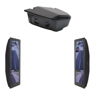
ARCOL eMirror System And Installation Manual
Camera monitor system
Hide thumbs
Also See for eMirror:
- System and installation manual (29 pages) ,
- User manual (6 pages) ,
- User manual (4 pages)
Table of Contents
Advertisement
Quick Links
Advertisement
Table of Contents

Related Manuals for ARCOL eMirror


Summary of Contents for ARCOL eMirror
- Page 1 Camera Monitor System System and Installation Manual English V 04/2022...
-
Page 2: Table Of Contents
Camera Monitor System Contents Page 1. System Description 2. Categories 2.1 eMirror Class II 2.2 eMirror Class IV 2.3 eMirror Class V 3. Electrical connections 4. Camera unit fixing points 5. Camera unit 5.1 Vehicle mounting position 5.2 Camera unit mounting Cat. II / IV 5.3 Camera unit mounting Cat. -
Page 3: System Description
Length 2,5 m 12V/24V power supply 12V/24V power supply cable length 2,5m cable length 2,5m Figure 1 Figure 2 eMirror system Cat. II / IV / V Class V Camera 12,3" Monitor Class IV Camera Class II Class II Camera Class IV... -
Page 4: Categories
Camera Monitor System 2. Categories 2.1. eMirror Class II The Class II field of vision of the main mirror device shows the driver a width of 5 m which is delimited by a plane parallel to the vertical longitudinal median plane and passing through the outermost point of the vehicle from a point 30 m behind the driver's ocular points towards the horizon. -
Page 5: Electrical Connections
Switch Class V - 12V / 24 V The eMirror system must always be connected to the battery. The system will display the image in less than 7 seconds once the System ON/OFF signal goes from 0V to 12V/24V. The System ON/OFF line must remain in the ON position for 420 seconds after the vehicle is turned off. -
Page 6: Camera Unit
Camera Monitor System 5. Camera Unit 5.1 Vehicle mounting position The positioning and placement of the cameras is essential for the correct functioning of the system. It is recommended that the camera unit is fully coupled to the bodywork, avoiding leaving a gap between the two as elements may collide with it and become trapped causing damage to the system. - Page 7 Camera Monitor System 5.2 Camera unit mounting Cat. II /IV Step 1 Step 2 1.1 Loosen with 3 mm hexagon wrench 2.1 Pass cables through the bracket 1.2 Remove cover Minimum cable bending radius Step 3 Step 4 4.1 Making connections 3.1 Fasten with 6 mm hexagonal wrench...
-
Page 8: Camera Unit Mounting Cat. Ii
Camera Monitor System 5.3 Camera unit mounting Cat. II / V Step 1 Step 2 1.1 Loosen with 3 mm hexagon wrench 2.1 Remove Class V Camera 1.2 Remove cover Step 3 3.1 Pass cables through the bracket Minimum cable bending radius... - Page 9 Camera Monitor System Step 7 Step 6 6.1 Making connections 7.1 Fasten cables Heated camera cat. V Camera cat. V Heated camera cat. II Camera cat. II Step 8 8.1 Place cover 8.2 Fasten with 3mm hexagonal wrench English V 04/2022...
-
Page 10: Camera Unit Mounting Cat. Ii / Iv
Camera Monitor System 5.4 Camera unit mounting Cat. II / IV / V Step 1 Step 2 2.1 Remove Class V Camera 1.1 Loosen with 3 mm hexagon wrench 1.2 Remove cover Step 3 3.1 Pass cables through the bracket... - Page 11 Camera Monitor System Step 7 Step 6 6.1 Making connections 7.1 Fasten cables Heated camera cat. V Camera cat. V Heated camera cat. IV Camera cat. II Camera cat. IV Heated camera cat. II Step 8 8.1 Place cover 8.2 Fasten with 3mm hexagonal wrench...
-
Page 12: Monitor
Camera Monitor System 6. Monitor 6.1 Mounting position The positioning and placement of the monitor is essential for the correct operation of the system. The position of both monitors, on the driver and passenger sides, should be perpendicular to the horizontal plane passing through the centres of the monitor and the driver's eyes (see Figure 5). -
Page 13: Monitor Mounting
Step 4 4.1 Insert the monitor into the stand 3.1 Fasten cables 3.2 Place cover H2-cross recess **Optional VESA 35X75 fixing provided by Arcol Step 5 Step 6 6.1 Fasten 5.1 Find the right position *Mounting position, see page 7...
Need help?
Do you have a question about the eMirror and is the answer not in the manual?
Questions and answers