Table of Contents
Advertisement
Quick Links
Advertisement
Table of Contents

Related Manuals for Tesco 6330


Summary of Contents for Tesco 6330
- Page 1 OPERATIONS MANUAL METER SITE ANALYZER PRODUCT: CATALOG NO. 6330...
- Page 2 METER SITE ANALYZER OPERATIONS MANUAL CATALOG NO. 6330 © 2020 TESCO - The Eastern Specialty Company All Rights Reserved. Specifications are subject to change without prior notice. Revision TESCO – The Eastern Specialty Company 925 Canal Street Bristol, PA, 19007 Phone: 215.228.0500...
- Page 4 If no warranty period is specified below and signed by an authorized DISTRIBUTOR of TESCO, the Warranty Period shall be one (1) year. In no event shall this Warranty remain in effect for more than the stated Warranty Period plus two (2) months after the date of shipment.
- Page 5 The Warranty set forth herein shall NOT be effective unless: 1. Notice of defect is given to TESCO by phone, fax, email or mail as soon as the defect is discovered.
-
Page 6: Table Of Contents
TABLE OF CONTENTS TABLE OF CONTENTS 1.0 INTRODUCTION ....................... 1 1.1 Introduction ........................2 1.2 Contacting TESCO......................2 1.3 General Safety Summary ....................3 1.4 Description of Safety-related Icons ................... 3 1.5 Product Features ......................4 1.5.1 Key Features ..........................4 1.5.2... - Page 7 OPERATIONS MANUAL 3.3.2a Metrology ..........................15 3.3.2b Phasors ............................ 16 3.3.2c Waveforms ..........................17 3.3.2d Harmonics ..........................17 3.3.3 Main Menu ............................18 3.3.3.1 Manual Mode ......................... 19 3.3.3.1a Meter Test ........................19 3.3.3.1b Meter Test Results ......................22 3.3.3.1c CT Testing .......................... 24 3.3.3.1d Quick Test .........................
- Page 8 TABLE OF CONTENTS 4.1.1 Demand Test ............................43 4.1.1 Energy Test ............................44 4.2 CT Test ........................... 44 4.3 Sequence Test ........................ 45 5.0 MAINTENANCE ......................46 5.1 Introduction ........................47 5.2 Cleaning the Site Analyzer’s External Surface ..............47 5.3 Repair / Parts Replacement / Recalibration ..............
-
Page 10: Introduction
INTRODUCTION 1.0 INTRODUCTION 1.1 Introduction ................Error! Bookmark not defined. 1.2 Contacting TESCO..............Error! Bookmark not defined. 1.3 General Safety Summary ............Error! Bookmark not defined. 1.4 Description of Safety-related Icons ......... Error! Bookmark not defined. 1.5 Product Features ..............Error! Bookmark not defined. -
Page 11: Introduction
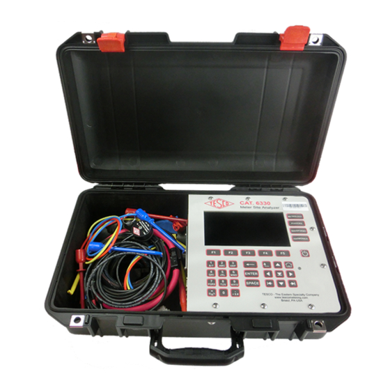
CTs, PTs, and other issues. If you want to be sure the customer is billed correctly and you are not losing revenue, you must test the whole site, not just the meter — this is where TESCO’s Meter Site Analyzer (Catalog No. 6330) comes in. -
Page 12: General Safety Summary
INTRODUCTION 1.3 General Safety Summary This manual contains information and warnings that must be observed to ensure safe operation and keep the Site Analyzer in a safe condition. Operation or service in conditions or in a manner other than specified could compromise safety. For the correct and safe use of the site analyzer, it is essential that both operating and service personnel follow accepted safety procedures in addition to the safety precautions specified, including proper PPE guidelines. -
Page 13: Product Features
1.5.3 Standard Unit These are the standard items included in the package: • 6330 TESCO Meter Site Analyzer • Optical pickup (1037-SA) with 9.84 ft. cable, Next Gen compatible • Battery charger (90W 19VDC output, 85 -264VAC input with 6 ft. cord) 1.5.4... -
Page 14: Optional Accessories
INTRODUCTION 1.5.5 Optional Accessories • SENSORLINK high voltage probe • 50 ft. extension cables for Rogowski coils • Diamond Level Support 1.6 General Specifications 1.6.1 Input Characteristics PARAMETERS DATA Supply Frequency 50/60Hz Power Supply Adaptor 19VDC, 4.74A Output Power 90W Max. 1.6.2 Dimensions PARAMETERS... -
Page 15: About This Operations Manual
OPERATIONS MANUAL 1.7 About this Operations Manual This manual provides complete information for setting up and operating the Site Analyzer. This document instructs the user on the following operations of the CAT. 6330: ▪ Setup ▪ Front Panel Features ▪... -
Page 16: Setup
SETUP 2.0 SETUP 2.1 Introduction ................Error! Bookmark not defined. 2.2 Unpacking and Inspection ............Error! Bookmark not defined. 2.3 Setup and Cooling Considerations .......... Error! Bookmark not defined. 2.3.1 Setup and Placement ................Error! Bookmark not defined. 2.4 Main Power Supply ..............Error! Bookmark not defined. tescometering.com +1 215 228 0500 support@tescometering.com... -
Page 17: Introduction
A packing list is included in the packaging. When you unpack the Site Analyzer, check for all the standard equipment listed and check the shipping order for any additional items ordered. Report any shortage to the place of purchase, your distributor, or directly to TESCO. 2.3 Setup and Cooling Considerations 2.3.1 Setup and Placement... -
Page 18: Main Power Supply
The Site Analyzer is fully battery powered and the battery can be charged in or outside of the unit from AC or DC. The battery can easily be swapped out. Additional chargers are available for purchase from TESCO or your distributor. BATTERY... -
Page 19: Functionality
OPERATIONS MANUAL 3.0 FUNCTIONALITY 3.1 Introduction ................Error! Bookmark not defined. 3.2 Panel Features ..............Error! Bookmark not defined. 3.2.1 Front Panel ....................Error! Bookmark not defined. 3.2.2 Side Panel ....................Error! Bookmark not defined. 3.2.3 Front Panel Buttons ................... Error! Bookmark not defined. 3.3 The Graphical User Interface (GUI) ......... - Page 20 FUNCTIONALITY 3.3.3.4b Users ..................Error! Bookmark not defined. 3.3.3.4c Colors/Beepers Options ............Error! Bookmark not defined. 3.3.3.4d Testing Options ..............Error! Bookmark not defined. 3.3.3.4e Calibration Options ............. Error! Bookmark not defined. 3.3.3.5 System Information..............Error! Bookmark not defined. 3.3.3.5a Temperature ................ Error! Bookmark not defined. 3.3.3.5b Configuration ..............
-
Page 21: Introduction
Front panel features (controls, displays, indicators) and side panel sections (terminals) are shown in Figure 3.2.1 and Figure 3.2.2 respectively. 3.2.1 Front Panel NUMBER DESCRIPTION LCD screen Function keys Keypad Fast access keys Power button Navigation buttons Table 3.2.1. CAT. 6330 Front Panel Sections +1 215 228 0500 tescometering.com support@tescometering.com... -
Page 22: Side Panel
Optical Pickup Terminal Ethernet Communication USB type-B port USB type-A ports Battery Compartment Table 3.2.2. CAT. 6330 Side Panel Sections 3.2.3 Front Panel Buttons SYMBOL DESCRIPTION • Selects the NEXT or PREVIOUS menu item • Moves the SELECTED LINE UP or DOWN •... -
Page 23: The Graphical User Interface (Gui)
Status Bar Screen Data Function Buttons Table 3.3.1. CAT. 6330 GUI Sections STATUS BAR ICONS These icons are located at the status bar of the screen. They are indicators of different network connections and temperature levels of the site analyzer. -
Page 24: Fast Access Functions
FUNCTIONALITY 3.3.2 Fast Access Functions SCREEN DESCRIPTION The “FAST” access buttons provide instant access to various measurements at any time. Pressing one of the buttons brings up the display regardless of what is shown on the screen. Pressing the same button again shows the previous screen. -
Page 25: Phasors
OPERATIONS MANUAL SCREEN DESCRIPTION PAGE 3 3.3.2b Phasors SCREEN DESCRIPTION Displays a phasor diagram for the active phases. Diagram is continuously updated. KEYPAD & FUNCTION KEYS: PRIMARY Switch to the primary reading. SECONDARY Switch to the secondary reading. HOLD Freeze the data acquisition. LIVE Change to showing live data. -
Page 26: Waveforms
FUNCTIONALITY 3.3.2c Waveforms SCREEN DESCRIPTION Displays live waveforms with recording functionality. KEYPAD & FUNCTION KEYS: HIDE V Hide or show the voltage waveforms. HIDE I Hide or show the current waveforms. Select the number of cycles to be N CYCLES displayed: 1, 2, 4, 8 Shift between ALL, Phase A, Phase B PHASE A... -
Page 27: Main Menu
OPERATIONS MANUAL SCREEN DESCRIPTION Voltage B and Current B, linear display with 1st harmonic suppressed in “dots” mode. 3.3.3 Main Menu SCREEN DESCRIPTION The MAIN MENU contains the core functions of the site analyzer. A site can be selected using the SITE dropdown box. Clicking the GPS LOCATE button will narrow the choices for SITE to those at the current GPS location. -
Page 28: Manual Mode
FUNCTIONALITY 3.3.3.1 Manual Mode SCREEN DESCRIPTION Manual Mode allows testing without specifying a site or test sequence. If MANUAL MODE a site was selected on the MAIN MENU, then the information on this screen will automatically be filled in. If no SITE was selected, then one can be selected here, or just a meter form and service can be manually set. - Page 29 OPERATIONS MANUAL SCREEN DESCRIPTION TEST LOADS Customer voltage is used for all tests. Uses customer load where the site analyzer is 1-CL measuring the voltage signal and the current (CUSTOMER signals from both the potential and the LOAD) current transformers. Load box provided current of TA at PF=1.0 is 2-FL (TA) used.
- Page 30 FUNCTIONALITY SCREEN DESCRIPTION C. TIMED REGISTER TEST TIMED REGISTER TEST This test prompts the user for the meter’s primary register value and runs a test for a predefined duration. Then, it prompts the user again for the meter’s primary register value. The system computes the meter’s registration using the difference of the two values.
-
Page 31: Meter Test Results
OPERATIONS MANUAL 3.3.3.1b Meter Test Results SCREEN DESCRIPTION This shows the numerical data and graphical representation of the data, METER TEST RESULT after completing the test. Test results can only be saved when a site was selected. TEST IN PROGRESS KEYPAD &... - Page 32 FUNCTIONALITY SCREEN DESCRIPTION REDO THE TEST REDO This will perform the test again with the same test parameters. Press to cancel the test and proceed to the sequence summary. REVIEW REVIEW THE TEST Look back at the test that was recently performed. Press to proceed to the sequence summary.
-
Page 33: Ct Testing
OPERATIONS MANUAL 3.3.3.1c CT Testing SCREEN DESCRIPTION CT TEST MODES CT TEST The CAT6330 provides a wide range of methods for testing CTs. The change in the secondary current is measured as the burden placed on the CT is BURDEN ONLY TEST increased. - Page 34 FUNCTIONALITY SCREEN DESCRIPTION CT TEST RESULTS BURDEN ONLY CT test results are presented for Ratio, Burden, Ratio with Burden, and Admittance tests. Soft keys provide many ways of looking at the test data. Each CT test will PASS • Measured current falls within the specified accuracy region (in a Burden Test) or inside the parallelogram (in a Ratio Test) even at low current.
- Page 35 OPERATIONS MANUAL SCREEN DESCRIPTION CT RATIO ONLY RATIO ONLY The ratio only test measures the complete set of CT parameters and displays them in numeric and graphical form. The data is also displayed on the IEEE accuracy parallelogram. CTs which meet the requirements of their accuracy class will be represented by points inside the parallelogram.
- Page 36 FUNCTIONALITY shows PARALLELOGRAM changes to PARALLELOGRAM plot PROBE PHASE ERROR when pressed. DONE or SAVE will be available DONE depending on whether a site has SAVE been selected. DATA Burden resistance ΔI (%) Measured current ACCURACY CLASS Accuracy class of CT BURDEN CLASS Burden class of CT USER-DEFINE LIMITS...
-
Page 37: Quick Test
OPERATIONS MANUAL 3.3.3.1d Quick Test SCREEN DESCRIPTION Perform a quick test, with Full Load Accuracy Test set as the default test. QUICK TEST ENTER Enter the Kh/Kt of the meter. Press to select the and press 3.3.3.1e Pulse Alignment Check SCREEN DESCRIPTION This will apply voltage and current to the meter so that the optical probe... -
Page 38: Sequence Testing
FUNCTIONALITY 3.3.3.2 Sequence Testing SCREEN DESCRIPTION Sequence testing is performed when there is more than one type of test to SEQUENCE TESTING execute. In this test, a sequence must be selected and To know how to perform a Sequence Test, proceed to section 4.3 Sequence Test. -
Page 39: Database
OPERATIONS MANUAL 3.3.3.3 Database SCREEN DESCRIPTION This contains information on sites registered in the Site Analyzer. The user can DATABASE create a new site and edit an existing record. Aside from the site, the user can also create and edit Meter, CT, and Customer information per site. The database also shows test results from Meter and CT tests. -
Page 40: Add/Edit Site
FUNCTIONALITY 3.3.3.3a Add/Edit Site SCREEN DESCRIPTION NEW/EDIT SITE Create new site information. Fill out the information and save it in the NEW SITE database. If the site info is for editing, the fields will be filled with pre-saved information of that site and the user can make changes. NEW SITE INFO KEYPAD &... -
Page 41: Add/Edit Meter
OPERATIONS MANUAL 3.3.3.3b Add/Edit Meter SCREEN DESCRIPTION Create new meter information. Fill out the information and save it in the NEW/EDIT METER database. If the existing meter info is for editing, the fields will be filled with pre-saved information of that meter and the user can make changes. KEYPAD &... -
Page 42: Add/Edit Ct
FUNCTIONALITY 3.3.3.3c Add/Edit CT SCREEN DESCRIPTION NEW CT NEW/EDIT CT Create new CT information. Fill out and save it in the database. A maximum of three (3) CTs can be added at a time. If the existing CT info is for editing, the fields will be filled with pre-saved information of that CT and the user can make changes and save them. -
Page 43: New/Edit Customer
OPERATIONS MANUAL 3.3.3.3d New/Edit Customer SCREEN DESCRIPTION NEW/EDIT CUSTOMER Create new customer information. Fill out the information and save it in the database. If the customer info is for editing, the fields will be filled with pre- saved information of that customer and the user can make changes. NEW CUSTOMER To save the changes, press to return to the New or Edit Site Info page... -
Page 44: Add/Edit Sequences
FUNCTIONALITY 3.3.3.3f Add/Edit Sequences SCREEN DESCRIPTION TEST SEQUENCES Add, edit, and delete test sequences. This allows the user a certain level of customization in the sequence. In adding or editing a test sequence, the user can re-arrange the tests with the MOVE DOWN and MOVE UP buttons. -
Page 45: Settings
OPERATIONS MANUAL 3.3.3.4 Settings SCREEN DESCRIPTION SETTINGS Change or update the options and settings for the site analyzer. KEYPAD & FUNCTION KEYS: Adjust screen brightness options GENERAL and select method of assigning IP address. USERS View name of user or technician. COLORS/BEEPER Change phase color assignments. -
Page 46: Users
FUNCTIONALITY 3.3.3.4b Users SCREEN DESCRIPTION Set the name of the user (or technician) and the system. The username will USERS be shown in the main menu after bootup. DATA This could be the technician’s name or any user USER NAME for that matter. -
Page 47: Testing Options
OPERATIONS MANUAL 3.3.3.4d Testing Options SCREEN DESCRIPTION TESTING OPTIONS Set an option whether to define a delay between tests in a sequence; wait until a user presses continue; or have no delay at all and have the succeeding tests execute immediately. The user can also set the default defined limits for CT testing. -
Page 48: System Information
FUNCTIONALITY 3.3.3.5 System Information SCREEN DESCRIPTION This is the menu to view information on the temperature, configurations, SYSTEM INFO serial numbers, software versions, and calibration of the system. KEYPAD & FUNCTION KEYS: Check the temperature of the TEMPS circuit, CTs, and battery. View configurations for current, CONFIGURATION frequency,... -
Page 49: Configuration
OPERATIONS MANUAL 3.3.3.5b Configuration SCREEN DESCRIPTION CONFIGURATION View information on the standard and load box. DATA MAX CURRENT Maximum current for the load box MIN CURRENT Minimum current for the load box MAX FREQ Maximum frequency for the load box MIN FREQ Minimum frequency for the load box THERMAL... -
Page 50: Software Versions
3.3.3.5e Calibration SCREEN DESCRIPTION CALIBRATION View calibration details of the site analyzer. Should the site analyzer need recalibration, please contact TESCO. Contact details are found in section 1.2 Contacting TESCO. DATA DATE Date when the site analyzer was last calibrated. -
Page 51: Configurations
OPERATIONS MANUAL 4.0 CONFIGURATIONS 4.1 Meter Test ................Error! Bookmark not defined. 4.1.1 Demand Test ..................... Error! Bookmark not defined. 4.1.1 Energy Test ....................Error! Bookmark not defined. 4.2 CT Test ................... Error! Bookmark not defined. 4.3 Sequence Test ................ Error! Bookmark not defined. +1 215 228 0500 tescometering.com support@tescometering.com... -
Page 52: Meter Test
CONFIGURATIONS 4.1 Meter Test SCREEN DESCRIPTION HOW TO PERFORM METER TEST: 1. If a site was preselected, the test parameters will be automatically filled in. Otherwise, manually input the parameters and select the test load and test type. 2. If an optical probe is attached to the meter, the meter’s pulse output can be aligned by pressing [PULSE ALIGN]. -
Page 53: Energy Test
OPERATIONS MANUAL 4.1.1 Energy Test SCREEN DESCRIPTION HOW TO PERFORM ENERGY METER TEST: STARTING METER READING 1. Press [START]. 2. Enter meter kWh and press the ENTER button. 3. Enter the meters demand register (kW) and press the ENTER button. ENDING METER READING 4.2 CT Test SCREEN... -
Page 54: Sequence Test
CONFIGURATIONS 4.3 Sequence Test SCREEN DESCRIPTION HOW TO PERFORM SEQUENCE TESTING: 1. Select a site in the Main Menu. This is required before Sequence Setup can be accessed. 2. Set the Sequence Name and Tolerance for the pass or fail criteria. The TA and Service can’t be changed as they were already configured in the chosen site. -
Page 55: Maintenance
OPERATIONS MANUAL 5.0 MAINTENANCE 5.1 Introduction ........................47 5.2 Cleaning the Site Analyzer’s External Surface ..............47 5.3 Repair / Parts Replacement / Recalibration ..............47 +1 215 228 0500 tescometering.com support@tescometering.com... -
Page 56: Introduction
MAINTENANCE 5.1 Introduction Most of the maintenance will be handled by the technical team from TESCO. The user can, however, perform the basic maintenance routine of cleaning the meter site analyzer’s external surface. 5.2 Cleaning the Site Analyzer’s External Surface Clean the exterior of the Site Analyzer using a soft cloth slightly dampened with either water or a non-abrasive mild cleaning solution that is not harmful to plastics.
Need help?
Do you have a question about the 6330 and is the answer not in the manual?
Questions and answers