Table of Contents
Advertisement
Quick Links
Advertisement
Table of Contents
Troubleshooting

Related Manuals for Tesco DTS-2990


Summary of Contents for Tesco DTS-2990
- Page 1 OPERATIONS MANUAL DESKTOP METER TEST STATION PRODUCT: DTS-2990...
- Page 2 DESKTOP METER TEST STATION OPERATIONS MANUAL DTS-2990 © 2019 TESCO - The Eastern Specialty Company All Rights Reserved. Specifications are subject to change without prior notice. Revision TESCO – The Eastern Specialty Company 925 Canal Street Bristol, PA, 19007 Phone: 215.785.2338 info@tescometering.com...
- Page 3 If no warranty period is specified below and signed by an authorized DISTRIBUTOR of TESCO, the Warranty Period shall be one (1) year. In no event shall this Warranty remain in effect for more than the stated Warranty Period plus two (2) months after the date of shipment.
- Page 4 The Warranty set forth herein shall NOT be effective unless: 1. Notice of defect is given to TESCO by phone, fax, email or mail as soon as the defect is discovered.
-
Page 5: Table Of Contents
2.3.1 Setup and Placement ..........................8 2.3.2 Airflow ..............................9 2.4 Main Power Supply ......................9 2.5 Utility Meter Insertion/Extraction ................... 10 3.0 DTS-2990 FUNCTIONALITIES ..................... 11 3.1 Introduction ........................12 3.2 Front Panel Features ...................... 12 3.2.1 Front Panel Sections ..........................12 3.2.2 Navigation Keys ............................ - Page 6 OPERATIONS MANUAL 3.3.3 MANUAL TEST ........................... 14 3.3.4 SINGLE TEST SETUP ........................... 16 3.3.5 TEST SELECTION ..........................17 3.3.6 SEQUENCE TESTING .......................... 17 3.3.7 PLC TEST ............................19 3.3.8 DISCONNECT TEST..........................19 3.3.9 TIME & USER INFORMATION ......................20 3.3.10 SYSTEM INFORMATION ........................21 3.3.11 NETWORK SETUP ..........................
- Page 7 TABLE OF CONTENTS 7.2 Test ..........................36 7.3 Software .......................... 36 7.4 Hardware ......................... 36 8.0 TROUBLESHOOTING ......................37 8.1 Troubleshooting ......................38 www.tescometering.com +1 215 785 2338 support@tescometering.com...
-
Page 8: Introduction
INTRODUCTION 1.0 INTRODUCTION Introduction ........................2 Contacting TESCO ......................2 General Safety Summary ....................3 Description of Safety-related Icons ..................3 Protective Earth / Grounding ..................... 3 Product Features ....................... 4 1.6.1 Key Features ............................4 1.6.2 Standard Features ..........................4 1.6.3... -
Page 9: Introduction
Tired of waiting for access to a production test board? Tired of wasting time going to another building to use test equipment? Need flexibility, state -of-the-art performance, and ease of use? If so, then TESCO’s revolutionary 2990 Desktop Meter Test Station (DTS-2990) is the answer to what you need. -
Page 10: General Safety Summary
INTRODUCTION General Safety Summary This manual contains information and warnings that must be observed to ensure safe operation and keep the Instrument in a safe condition. Operation or service in conditions or in a manner other than specified could compromise safety. For the correct and safe use of this device, it is essential that both operating and service personnel follow accepted safety procedures in addition to the safety precautions specified. -
Page 11: Product Features
OPERATIONS MANUAL Product Features 1.6.1 Key Features Precise Measurement Accuracy for Voltage, Current & Power o Simultaneous time and frequency domain measurements Accurate Voltage and Current Setting Digital Waveform Generator o Voltage Drive: 30-350V RMS, 490V PK (line to neutral) o Current Drive: 0.01A to 50A RMS, 75A PK o Arbitrary harmonically defined waveforms Automatic Generation of all ANSI C12.20-2016 waveforms... -
Page 12: Optional Features
INTRODUCTION 1.6.3 Optional Features A-Base Test Board Adapter 1180 K-Base Test Board Adapter Adapter for calibrating the unit Diamond Support with Calibration Service Stand-alone calibration of the unit Wedge (2490) and Mechanical Pickup (2480) for testing mechanical meters General Specifications 1.7.1 Input Characteristics... -
Page 13: About This Operations Manual
OPERATIONS MANUAL 1.8 About this Operations Manual This manual provides complete information for installing and operating the Instrument. This document instructs the user on the following operations of the DTS-2990: Installation Front Panel Features Graphical User Interface (GUI) ... -
Page 14: Installation
INSTALLATION 2.0 INSTALLATION 2.1 Introduction ........................8 2.2 Unpacking and Inspection ....................8 2.3 Set up, Airflow and Cooling Considerations ............... 8 2.3.1 Setup and Placement ..........................8 2.3.2 Airflow ..............................9 2.4 Main Power Supply ......................9 2.5 Utility Meter Insertion/Extraction ................... 10 www.tescometering.com +1 215 785 2338 support@tescometering.com... -
Page 15: Introduction
A packing list is included in the packaging. When you unpack the Instrument, check for all the standard equipment listed and check the shipping order for any additional items ordered. Report any shortage to the place of purchase to your distributor or directly to TESCO. 2.3 Set up, Airflow and Cooling Considerations 2.3.1 Setup and Placement... -
Page 16: Airflow
INSTALLATION 2.3.2 Airflow Take note of the Instrument’s airflow as seen in the illustration. This always for a table top, never on a rack. Please allow enough airspace at the side with at least half a meter for an effective airflow. -
Page 17: Utility Meter Insertion/Extraction
OPERATIONS MANUAL WARNING The Instrument should only be plugged to an AC outlet with a 90 – 120V voltage range to avoid damaging the Instrument. To avoid electrical shock, personal injury, or fire hazard, connect the factory-supplied three- conductor-line power cord to a properly grounded power outlet. During test operation, a two-conductor adapter or extension cord MUST NOT be used. -
Page 18: Dts-2990 Functionalities
FUNCTIONALITIES 3.0 DTS-2990 FUNCTIONALITIES 3.1 Introduction ........................12 3.2 Front Panel Features ...................... 12 3.2.1 Front Panel Sections ..........................12 3.2.2 Navigation Keys ............................13 3.3 The Graphical User Interface (GUI) .................. 13 3.3.1 Graphical User Interface (GUI) Screens .................... 13 3.3.2... -
Page 19: Introduction
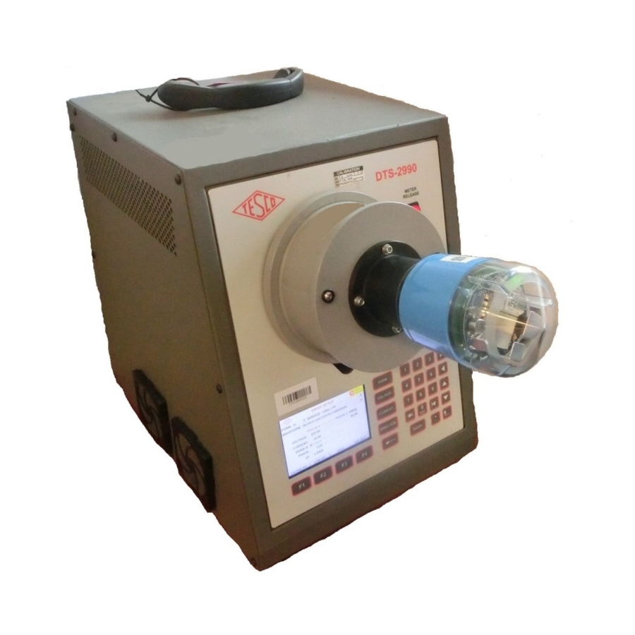
DESCRIPTION Air inlet Function keys LCD screen Meter socket Meter release button Optical Pickup port Disconnection Test indicators Power button Keypad Navigation buttons Table 3.2.1. DTS-2990 Front Panel Sections Figure 3.2.1a DTS-2990 Front Panel +1 215 785 2338 www.tescometering.com support@tescometering.com... -
Page 20: Navigation Keys
The user interface is divided into four sections. In the screen, any field that is grayed out cannot be changed or accessed by the user. NUMBER DESCRIPTION Screen Title Drive Indicator Screen Data Function Buttons Table 3.3.1. DTS-2990 GUI Sections www.tescometering.com +1 215 785 2338 support@tescometering.com... -
Page 21: Main Menu
OPERATIONS MANUAL 3.3.2 MAIN MENU SCREEN DESCRIPTION 3.3.2.1 MAIN MENU The MAIN MENU screen consists of the following function buttons: MANUAL, TESTS, & SETUP. Press arrow keys to navigate through the main menu or directly press the function keys. KEYPAD & FUNCTION KEYS: Press to open the DRIVE SETUP screen Press to open the TEST SELECTION screen... - Page 22 FUNCTIONALITIES SCREEN DESCRIPTION 3.3.3.2 DRIVE ACTIVE DRIVE SETUP This screen displays the operational statistics of the test being conducted. FUNCTION KEYS Press to open the TEMPERATURES TEMPERATURES screen DATA VOLTAGE Voltage measured by Instrument Voltage phase angle with respect to V PHASE reference frame CURRENT...
-
Page 23: Single Test Setup
OPERATIONS MANUAL 3.3.4 SINGLE TEST SETUP SCREEN DESCRIPTION 3.3.4.1 SINGLE TEST SETUP METER INFO This enables the configuration of the desired single test to be conducted. Accuracy toggled FUNCTION KEYS Press to enable service voltage to the VOLTAGE ON socket Press to align optical pickup. -
Page 24: Test Selection
FUNCTIONALITIES 3.3.5 TEST SELECTION SCREEN DESCRIPTION TESTS 3.3.5.1 TESTS The TEST SELECTION screen consists of the following function buttons: MANUAL, PLC, & DISCONNECT. Press arrow keys to navigate through the menu or directly press the function keys. KEYPAD & FUNCTION KEYS: Press to open METER INFO screen. - Page 25 OPERATIONS MANUAL SCREEN DESCRIPTION 3.3.6.3 SEQUENCE ACTIVE SEQUENCE SETUP This screen shows the live results of the tests. KEYPAD & FUNCTION KEYS Press to cancel the test process and CANCEL return to SEQUENCE SETUP screen Press to open the MEASUREMENTS screen RESULTS Press to show test results...
-
Page 26: Plc Test
FUNCTIONALITIES 3.3.7 PLC TEST SCREEN DESCRIPTION 3.3.7.1 PLC TEST PLC TEST PLC or Power Line Carrier test is for testing wired communication systems such as TWACS, etc. It bypasses the internal voltage and generation circuits. KEYPAD & FUNCTION KEYS Press to enable service voltage only to VOLTAGE ON socket Press to enable service voltage and load... -
Page 27: Time & User Information
DHCP server TIME ZONE Enter local time zone here 3.3.9.3 USER INFORMATION USER INFORMATION The default user name is “Tesco”. This can only be updated through TMA software. KEYPAD & FUNCTION KEYS: BACK Press to return to SETUP MENU screen... -
Page 28: System Information
FUNCTIONALITIES 3.3.10 SYSTEM INFORMATION SCREEN DESCRIPTION 3.3.10.1 SYSTEM INFORMATION SYSTEM INFORMATION This screen displays information about the hardware configurations, firmware revision levels and network configuration SYSTEM/MODULE INFORMATION TAB KEYPAD &FUNCTION KEYS Press to open the STANDARD NEXT INFORMATION tab Press to open the NETWORK SETUP NETWORK dialog box DATA... -
Page 29: Network Setup
OPERATIONS MANUAL CONTROLLERS TAB SYSTEM INFORMATION KEYPAD &FUNCTION KEYS (WAVEFORM GENERATOR) Proceeds to the SYSTEM INFORMATION NEXT Press to open the NETWORK SETUP NETWORK dialog box DATA Displays the serial number and software SOCKET 1 version of the socket 3.3.11 NETWORK SETUP SCREEN DESCRIPTION... -
Page 30: Remote Operations
REMOTE OPERATIONS 4.0 REMOTE OPERATIONS 4.1 Introduction ........................24 4.2 Installation ........................24 4.3 Network Configuration ....................24 4.4 Functionalities ......................... 24 4.4.1 NETWORK VIEW ............................. 24 4.4.2 TEST ................................ 25 4.4.3 METER DATABASE ..........................25 4.4.4 WAVEFORM SETUP ..........................25 4.4.5 TEST SEQUENCE ............................. -
Page 31: Introduction
Manual section 2.3.3 Network Discovery (NET SCAN) for more details. Once the list is filled, look for the DTS-2990 model and check if the device is online or offline. If offline, the device needs to be manually turned on. If online, click the device to enable the TEST and MANUAL TEST tabs. -
Page 32: Test
REMOTE OPERATIONS 4.4.2 TEST SCREEN DESCRIPTION TEST This is where the test is conducted. Results will also be displayed here as the test is being executed. For more details on the configurations for the test, please refer to the TMA Operations Manual section 2.3.6 TEST. -
Page 33: Test Sequence
OPERATIONS MANUAL 4.4.5 TEST SEQUENCE SCREEN DESCRIPTION TEST SEQUENCE This is used to configure test sequences. It allows creating, copying, and deleting test sequences, as well as setting up complex test scenarios that can be run on the TEST panel. For more details on test sequence configuration, please refer to the TMA Operations Manual section 2.3.9 TEST SEQUENCE TAB. -
Page 34: Maintenance
MAINTENANCE 5.0 MAINTENANCE 5.1 Introduction ........................28 5.2 Replacing the Fuse ......................28 5.3 Cleaning the Air Filters ..................... 29 5.4 Cleaning the Instrument External Surface ................ 30 www.tescometering.com +1 215 785 2338 support@tescometering.com... -
Page 35: Introduction
Cleaning the Instrument External Surface 5.2 Replacing the Fuse The power fuse IS accessible from the Instrument’s rear panel. See Figure 5.2. Figure 5.2 DTS-2990 Fuse Location WARNING To avoid electrical shock or personal injury, ensure that the Instrument is switched off and disconnected by removing the line power cord from the power input socket before attempting to access the power fuse. -
Page 36: Cleaning The Air Filters
250V 5.0A 5.3 Cleaning the Air Filters The fan air filters are accessible from the left-side front of DTS-2990. See Figure 5.3a. CAUTION Damage caused by overheating may occur if the area around the fan is restricted, the intake air is too warm, or the air filter becomes clogged. The air filter must be removed and cleaned at least every 30 days or more frequently if the Instrument is operated in a dusty environment. -
Page 37: Cleaning The Instrument External Surface
6. Reinstall the retainer in the fan guard. The retainer is snapped on the four sides for the fan guard. Figure 5.3b: DTS-2990 Fan Filter Assembly 5.4 Cleaning the Instrument External Surface Clean the exterior of the instrument using a soft cloth slightly dampened with either water or a non-abrasive mild cleaning solution that is not harmful to plastics. -
Page 38: Configurations
CONFIGURATIONS 6.0 CONFIGURATIONS 6.1 Single Test ........................32 6.2 Sequence Test ........................32 6.3 Disconnect Test........................ 33 6.4 PLC Test ........................... 34 www.tescometering.com +1 215 785 2338 support@tescometering.com... -
Page 39: Single Test
OPERATIONS MANUAL 6.1 Single Test SCREEN STEPS 1. From the MAIN MENU, press to access MANUAL TEST. 2. Configure the Drive Setup. Once everything is set, press to access METER INFO. SOCKET. 3. Enter the meter’s details and press to proceed with the SINGLE TEST SETUP. -
Page 40: Disconnect Test
CONFIGURATIONS 6.3 Disconnect Test SCREEN STEPS 1. From the MAIN MENU, press to access TEST DISCONNECT DISCONNECT SELECTION. TEST TEST JAW 2 JAW 4 JAW 2 JAW 4 2. Press to enter DISCONNECT TEST. The green DISCONNECT TEST indicator will turn on. 3. -
Page 41: Plc Test
OPERATIONS MANUAL 6.4 PLC Test SCREEN STEPS 1. From the MAIN MENU, press to access TEST SELECTION. 2. Press to access PLCT TEST. 3. Press to enable service voltage only to socket or press to enable both service voltage and current to socket. -
Page 42: Frequently Asked Questions
FREQUENTLY ASKED QUESTIONS 7.0 FREQUENTLY ASKED QUESTIONS 7.1 Introduction ........................36 7.2 Test ..........................36 7.3 Software .......................... 36 7.4 Hardware ......................... 36 www.tescometering.com +1 215 785 2338 support@tescometering.com... -
Page 43: Introduction
1.6.2 Standard Features. 7.3 Software 1. How can I obtain the firmware update file? You can directly contact TESCO through phone or email. For the contact details, see Section 1.2 Contacting TESCO. 2. When should I update the software? Updates are managed by TESCO. For contact details, see section 1.2 Contacting TESCO. -
Page 44: Troubleshooting
TROUBLESHOOTING 8.0 TROUBLESHOOTING 8.1 Troubleshooting ......................38 www.tescometering.com +1 215 785 2338 support@tescometering.com... -
Page 45: Troubleshooting
Make sure you hold the meter in place until the METER RELEASE indicator light turns on. For more information on troubleshooting, please contact TESCO. See section 1.2 Contacting TESCO for contact details. +1 215 785 2338 www.tescometering.com...
Need help?
Do you have a question about the DTS-2990 and is the answer not in the manual?
Questions and answers