Table of Contents
Advertisement
Advertisement
Table of Contents

Subscribe to Our Youtube Channel
Related Manuals for Tesco Knopp KATC-C1


Summary of Contents for Tesco Knopp KATC-C1
- Page 1 OPERATING INSTRUCTIONS for the TYPE KATC-C1 AUTOMATIC TRANSFORMER COMPARATOR Serial Number: _______ Leaflet Number 2-048 Revision A April 2014 Knopp Incorporated 1307 – 66th Street Emeryville, California 94608 (510) 653-1661 (800) 227-1848 (510) 653-2202 (FAX)
-
Page 2: Table Of Contents
Table of Contents General Information .................. 1 Specifications .................... 2 Installation ....................4 Type KCTS Current Transformer Testing System ..........4 Operation ....................6 Description of Controls ..................6 ON/OFF Switch ..................6 REFERENCE TRANSFORMER Switch ............6 TRANSFORMER-UNDER-TEST Switch ............6 RATIO ERROR Switch ................ - Page 3 INVALID SWITCH SETTING ..............11 SET CURRENT TO 0.00 ................11 XMTR not empty ..................11 *** (Over-range Indicators) ..............11 Troubleshooting and Repair ..............12 Doesn't Work The First Time ................12 Identical Or Near Zero Results ................12 Inaccurate Test Current Display ...............
-
Page 4: General Information
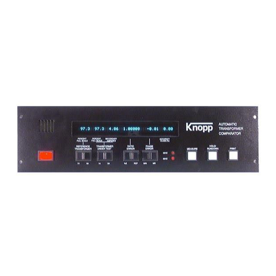
Chapter General Information The Knopp Automatic Transformer Comparator (KATC-C1) is used to measure the ratio and phase angle errors of current transformers with respect to a "standard" or "precision" transformer. This microprocessor-based instrument automatically selects the optimum measurement range, computes the results, and digitally displays several values, including: ... -
Page 5: Specifications
Chapter Specifications Input Power: 120 VAC, 50/60 Hz, less than 0.2 A Test Frequency: 50 or 60 Hz Test Current Range: 5% to 500% of selected range (1 or 5 amperes) 100% to +1000% (0 to 10 Ratio Correction Factor) Ratio Error Range: 1000 to +1000 minutes Phase Error Range:... - Page 6 RS-232 Serial Communications Port: 1200 or 9600 baud (user selectable) 8 Data Bits No Parity 2 Stop Bits Bi-directional KATC-C1 Instructions Page 3 04/14...
-
Page 7: Installation
Chapter Installation The KATC-C1 Comparator is designed for use as a stand-alone unit, it can be purchased as part of a complete test system, or it can be retrofitted into existing equipment. This chapter describes installa- tion of the KATC-C1 into various pieces of test equipment and its use in a stand-alone environment. Type KCTS Current Transformer Testing System Typically, the KCTS is shipped with the KATC-C1 already installed. - Page 8 KATC-C1 and the “5” terminal should be connected to E-bar on the KATC-C1. Ensure that the jumper from E-bar to the red binding post (DM) remains in place. It is important that all connections are clean and tight and that wire of sufficient gauge (#6) is used. Connect the lead marked “S”...
-
Page 9: Operation
Chapter Operation Description of Controls ON/OFF Switch Controls 120 VAC power to the KATC-C1. REFERENCE TRANSFORMER Switch Used to configure the KATC-C1 for use with reference (precision) transformers with 1 or 5 ampere secondaries. Do not change this switch with current applied to the KATC-C1. TRANSFORMER-UNDER-TEST Switch Used to configure the KATC-C1 for testing transformers with 1 or 5 ampere secondaries. -
Page 10: Hold/Rundown Push-Button
RUNUP mode causes the KATC-C1 to not take any measurements, instead the KATC-C1 selects its highest internal error range. This mode is used while the test current is being adjusted to mini- mize chances of damage to the comparator. This push-button is also used to reset the KATC-C1 after an error that caused an "alarm"... - Page 11 In the MEASURE mode the KATC-C1 is constantly calculating and displaying accuracy measurements and thus does not react as quickly to large changes in current. While we recommend using the RUNUP mode to set the test current and then pressing MEASURE to begin taking measurements, it is possible to change the test current while in the MEASURE mode.
-
Page 12: One-To-One Test
One-to-One Test The One-to-One test verifies proper operation of the KATC-C1 measurement circuitry. The connections shown below are to be used if the KATC-C1 is not used with a Knopp Transformer Test System, or if the KATC-C1 has been removed from a test system for troubleshooting. If the KATC-C1 is installed in a Knopp Transformer Test System, see the instruction manual included with that unit for information on running the One-to-One test. -
Page 13: Freq. Counter - No Finish
Freq. Counter – no Finish This message is similar to the message above except that it indicates that the KATC-C1 was able to start taking a measurement but was unable to complete the process. REF. COUNTER = 0 This message indicates that zero crossings were detected but that there have not been any counts received from the Counter Card #6. -
Page 14: Error Current Too High
ERROR CURRENT TOO HIGH The Error Current is defined as the difference between the secondary currents of the Reference Trans- former and the Transformer-Under-Test. If the Error Current exceeds 1.5 amperes the KATC-C1 will display this message and attempt to remove test current by opening the interlock and initiating a run down of test current. -
Page 15: Troubleshooting And Repair
Chapter Troubleshooting and Repair You Can Contact Knopp At: (800) 227-1848 or (510) 653-1661 Prior to initiating any repair of the KATC-C1, we encourage you to call us at one of the numbers listed above. Quite often, after hearing a brief description of the problem, we are able to identify the failed component and save you significant amounts of time. -
Page 16: Inaccurate Test Current Display
Inaccurate Test Current Display If the display of the Reference Test Current seems to be inaccurate, connect an AC ammeter between the rear panel "S" terminal and the lead connected to that terminal. Then adjust R9 on Card 2 [accessed through the rear panel] inside the KATC-C1 until the display of Reference Test Current agrees with the ammeter. -
Page 17: Other Features
Other Features Serial (RS-232C) Communications Port The Knopp KATC-C1 Automatic Transformer Comparator includes a standard RS-232 Serial Communications Port. This port can be used to send "Remote Commands" to the KATC-C1 from an external computer. The port can also be used to transfer test result data from the KATC-C1 to the computer. -
Page 18: Serial Port Baud Rate
Serial Port Baud Rate The Serial Port is set to communicate at 9600 baud. Other communication parameters are: eight (8) data bits, no parity, and two stop bits. Remote Commands For true remote operation, your computer can send commands to the KATC-C1. These commands can cause the KATC-C1 to perform various functions including: run-down of the test current, initiate a measurement, transfer of test result data to the computer, and a quick transfer of test current to the computer. -
Page 19: Rs-232 Data Record Formats
This command causes the KATC-C1 to send a reduced printout through the serial port. The reduced printout contains only test result data, no heading information is included. This is done to speed the transfer of data from the KATC-C1 to the computer. An example of this printout is also included in the next section. -
Page 20: Ratio Error And Minutes
RATIO ERROR AND MINUTES ASCII format: {CR}{LF} {CR}{LF} CT TEST; REF. TRANSFORMER SEC.: X AMPS; FREQUENCY: XX HZ. {CR}{LF} {CR}{LF} REF. {CR}{LF} TEST TEST TEST RATIO PHASE ACCURACY {CR}{LF} CURRENT CURRENT CURRENT ERROR ERROR CLASS {CR}{LF} (AMPS) (MINUTES) {CR}{LF} XXX.X XXX.X XX.XX ±XXX.XXX... - Page 21 +-------+ ¦*¦#¦*¦#¦ +-------+ Notes: When the TUT Test Current Switch is set to 1 ampere, the decimal point for the TUT TEST CURRENT (AMPS) printout is shifted one digit to the left (X.XXX). KATC-C1 Instructions Page 18 04/14...
-
Page 22: Ratio Error And Milliradians
RATIO ERROR AND MILLIRADIANS ASCII format: {CR}{LF} {CR}{LF} CT TEST; REF. TRANSFORMER SEC.: X AMPS; FREQUENCY: XX HZ. {CR}{LF} {CR}{LF} REF. {CR}{LF} TEST TEST TEST RATIO PHASE ACCURACY {CR}{LF} CURRENT CURRENT CURRENT ERROR ERROR CLASS {CR}{LF} (AMPS) (MILLIRAD.) {CR}{LF} XXX.X XXX.X XX.XX ±XXX.XXX... - Page 23 +-------+ ¦*¦#¦*¦#¦ +-------+ Notes: When the TUT Test Current Switch is set to 1 ampere, the decimal point for the TUT TEST CURRENT (AMPS) printout is shifted one digit to the left (X.XXX). KATC-C1 Instructions Page 20 04/14...
-
Page 24: Ratio Correction Factor And Minutes
RATIO CORRECTION FACTOR AND MINUTES ASCII format: {CR}{LF} {CR}{LF} CT TEST; REF. TRANSFORMER SEC.: X AMPS; FREQUENCY: XX HZ. {CR}{LF} {CR}{LF} REF. {CR}{LF} TEST TEST TEST RATIO PHASE ACCURACY {CR}{LF} CURRENT CURRENT CURRENT CORR. ERROR CLASS {CR}{LF} (AMPS) FACTOR (MINUTES) {CR}{LF} XXX.X XXX.X... - Page 25 +-------+ ¦*¦#¦*¦#¦ +-------+ Notes: When the TUT Test Current Switch is set to 1 ampere, the decimal point for the TUT TEST CURRENT (AMPS) printout is shifted one digit to the left (X.XXX). KATC-C1 Instructions Page 22 04/14...
-
Page 26: Ratio Correction Factor And Milliradians
RATIO CORRECTION FACTOR AND MILLIRADIANS ASCII format: {CR}{LF} {CR}{LF} CT TEST; REF. TRANSFORMER SEC.: X AMPS; FREQUENCY: XX HZ. {CR}{LF} {CR}{LF} REF. {CR}{LF} TEST TEST TEST RATIO PHASE ACCURACY {CR}{LF} CURRENT CURRENT CURRENT CORR. ERROR CLASS {CR}{LF} (AMPS) FACTOR (MILLIRAD.) {CR}{LF} XXX.X XXX.X... - Page 27 +-------+ ¦*¦#¦*¦#¦ +-------+ Notes: When the TUT Test Current Switch is set to 1 ampere, the decimal point for the TUT TEST CURRENT (AMPS) printout is shifted one digit to the left (X.XXX). KATC-C1 Instructions Page 24 04/14...
-
Page 28: Reduced (Two-Line) Printout
REDUCED (TWO-LINE) PRINTOUT This section describes the reduced printout which is available by sending the KATC-C1 the reduced printout command from a computer. This command is described in a preceding section. The purpose of the command is to minimize time required to obtain test result data from the KATC-C1. No heading information or descriptive wording is included in this printout. -
Page 29: Test Current Output
TEST CURRENT OUTPUT This section describes the test current output, which is available by sending the KATC-C1 the test current command from a computer. This command is described in a preceding section. The purpose of the command is to allow use of the KATC-C1 in an automated environment. In such an environment it may be useful to know the present value of the transformer-under-test secondary current as an aid in automatically adjusting the test current to the desired value. -
Page 30: Warranty
Chapter Warranty The Knopp Type KATC-C1 Automatic Transformer Comparator is warranted against defects in materials and workmanship for a period of ONE YEAR. If the KATC-C1 does not perform in accordance with stated operating specifications during the warranty period, necessary parts and assistance will be supplied under warranty to restore the equipment to service. - Page 31 I N D E X Identical Or Near Zero Results ......... 12 *** (Over-range Indicators) ..........11 Input Power ................ 2 Installation ................4 interlock ................12 Interlock ................2 INVALID SWITCH SETTING ........11 Accuracy ................2 Accuracy Class ..............2 AUTORANGING .............
- Page 32 I N D E X Performing ..............7 test current adjust slowly ..............7 Serial (RS-232) Communications Port Test Current ................ 2 XMTR not empty ............11 Transformer-Under-Test Serial (RS-232C) Communications Port ......14 Connecting ..............7 serial (RS-232C) input/output port ........1 Troubleshooting and Repair ..........
Need help?
Do you have a question about the Knopp KATC-C1 and is the answer not in the manual?
Questions and answers