
Subscribe to Our Youtube Channel
Related Manuals for RBM Kilma Set Touch 2.0


Summary of Contents for RBM Kilma Set Touch 2.0
- Page 1 Rev. Manual 03 - firmware version 1.49 del 16/01/2023 TOUCH SCREEN DISPLAY with built-in Wi-Fi interface and temperature and humidity sensor. USER GUIDE...
-
Page 2: Table Of Contents
INDEX Rev. Manual 03 - firmware version 1.49 del 16/01/2023 TOUCH SCREEN DISPLAY with built-in Wi-Fi interface and temperature and humidity sensor. INTRODUCTON 8. ADVANCED SETTINGS USER GUIDE 1. ZONES 8.1 Echo Display 1.1 Zones with Air-Quality Sensor 8.2 Change Alpha/Beta Mode (VOC) 8.3 Reread Master 2. -
Page 3: Introducton
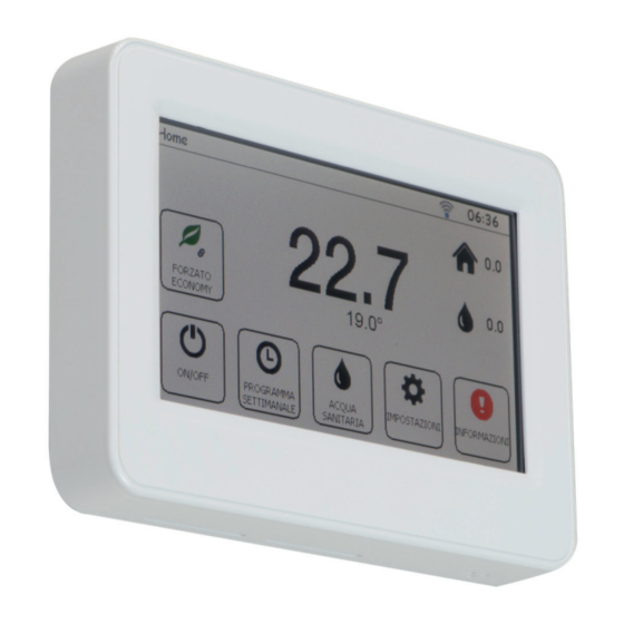
The buttons and icons will be explained in detail below. INTRODUCTION The touch screen display is a user-friendly interface allowing you to use the controller of the system it is installed on. The display CAUTION: The Wi-Fi settings are provided separately in Annex I at the end of this document! has a Wi-Fi interface to connect to the remote management system and a temperature and humidity sensor to manage the zone of the system where it is installed. - Page 4 Clicking any of the zones opens the zone settings screen. The example shows “Zona 1”: • View the humidity % (if there is a humidity sensor); • Clicking the “Adjust set point” button or else clicking the current ambient temperature of the zone once, grants access to the “Set Temperature”...
- Page 5 From the screen displayed in the following Image, you may Override the work mode of the zone to Comfort, Economy or Off. - Clicking the Timer Button from the screen displayed in Image 12 grants access to the Weekly Program of the timer associated By leaving Automatic, the work mode of the zone remains that defi...
-
Page 6: Zones With Air-Quality Sensor
The NUM button grants access both to numbers and special characters. Once the description has been modifi ed, press the Clicking the Comfort Button allows you to adjust the set point to activate the Comfort mode: Button with the green tick to confi rm or the one with the red X to undo the changes and exit the menu. CAUTION: If the name of the zone was selected among the default descriptions and not among the free ones, the name cannot be edited from the display, and therefore the pen to the right of the zone name will not be displayed. -
Page 7: Timers
Since the CO detected is lower than the limit of Economy (800 ppm) the fi rst threshold remains that of Economy mode, whereas Selecting the timer that you want to make changes to opens the screen of the selected timer where different hourly programming if the threshold is exceeded, the limit becomes 1500 ppm, namely that of the Comfort mode. - Page 8 Once changes have been made in Set Variation, press the Confi rm Button to go back to the previous screen saving the changes Press the Confi rm Button to go back to the Weekly Program screen. Click the Edit Parameters Button to separately modify or else press Undo to cancel them: Saturday and Sunday.
-
Page 9: Mechanical Extract
Lastly, the names of the timers can be edited directly from the display by clicking the pen to the right of the words “Camera 7”: Clicking the MEV Button opens the MEV List screen if the system manages more than one MEV: Image 32: Screen to edit the name of the timer Image 35: “MEV List”... -
Page 10: Heat/Cool And On/Off System Switch
Pressing the Exit Button returns to the MEV List screen and then to the Home page. Lastly, the names of the MEV itself can be edited directly from the display by clicking the pen to the right of the words “Camera 5”: If by selecting the MEV Button the following image is displayed, it means that the main switch to enable the MEV is off or that the timer program associated to the MEV is at off: Image 41: Screen to edit the name of the MEV... -
Page 11: Heat-Cool System Switch
Within the “System Switch-ON” menu, you may switch on the system by clicking the selector in the Enable System icon and setting it at ON (Image 43), or else switch off the system by setting the selector at OFF (Image 44). When the selection has been made, press the Exit Button to go back to the Home page. -
Page 12: Domestic Hot Water
Only if both seasons can be set will both be displayed in the System Switch-On Menu: Image 52: System Switch-on Screen Image 49: “System Switch-on” screen of a Summer and Winter system at ON 5. DOMESTIC HOT WATER The Domestic hot water button is only displayed if the controller is programmed for its management: Image 50: “System Switch-on”... -
Page 13: Alarms
From this screen you may: If production of domestic hot water was paired to a timer when programming the controller, the “DHW Timer” button appears on the left of the Comfort Button: • Press the DHW Enable Button selector, enable (ON) or disable (OFF) production of domestic hot water; •... -
Page 14: Settings
CHANGE HOMEPAGE The Change Homepage Button allows you to view the Thermal Power Station Home for the installer: Image 61: “Home” page without alarms in progress CAUTION: The installer is required to clear the alarms. Image 63: Thermal Power Station Home page If an installer password has been set (System Settings), they will be prompted to continue: 7. - Page 15 Clicking the desired circuit opens the following screen: Image 68: Circuit screen detail By clicking the Edit Button, if the Winter Button is selected, you may only edit the set point of the Economy and Comfort curves: Image 66: Winter Circuit screen Clicking the Summer Button will open: Immagine 69: Impostazione dei valori delle curve invernali...
-
Page 16: Update Via Network
It is not possible to edit on this page, but it displays: It is not possible to edit on this page, but it displays: • the set point temperature of each generator • the values (°C) and the descriptions of the free temperatures detected and the input they are connected to (ChA); •... -
Page 17: Screen Brightness
Image 76: Screen showing the latest update available Image 80: Screen that appears if the update is respect to the current/installed version. interrupted while overwriting the fi rmware. RETRY means to try again to download the update via Wi-Fi, while DFU means proceed with the update via USB (operation to be carried out by a specialised technician). -
Page 18: Advanced Settings
ECHO DISPLAY 8. ADVANCED SETTINGS The Echo Display Button allows you to virtually interact with the controller by viewing the controller itself on the touch screen and operating the same buttons (+; -; ESC and OK) as indicated in the following image: CAUTION: Only access this page if required and guided by a skilled technician. -
Page 19: Reread Master
REREAD MASTER The Reread Master Button allows you to reread the settings on the controller board which the display is connected to and if different, changes will also be made immediately to the touch screen display: Image 87: Home page from display 2 Image 90: Screen displayed during rereading of the board Image 88: Thermal Power Station Home page from... -
Page 20: Installer Password
INSTALLER PASSWORD Clicking the Installer Password Button allows you to set the new Installer password (which corresponds to the System Settings password) in order to limit access to the Thermal Power Station Home page: Image 96: New password set Even entering password 00000, you will still be prompted to enter the Advanced settings menu. Image 93: Screen to set installer password Entering password 00000 opens the following screen: Image 94: Password removed... -
Page 21: Annex I - Wi-Fi Connection
the display scans the available networks: ANNEX I – WI-FI CONNECTION Inside the User Settings screen accessed from the Home page: Image IV: Scanning of available Wi-Fi networks Once the Select Wi-Fi Network screen has been displayed, by pressing the “UP” and “DOWN” buttons, select the network you Image I: User Settings screen want to connect the display to and press “SELECT”... -
Page 22: Advanced Settings
When you click “OK” (if the password is correct) the display will again show the Wi-Fi Connection Management screen. Various ADVANCED SETTINGS texts will appear in the Status parameter: Clicking Advanced Settings displays two more Buttons: “Addresses Setting” and “Interface management”. •... -
Page 23: Wi-Fi Connection Of Beta Display
WI-FI CONNECTION OF BETA DISPLAY If you enter the Wi-Fi Connection from a Beta display (second display of the system), the following screen will appear: Image XI: Interface Management Screen It has the following buttons: • WIFI OFF: means that the display interface is off; Image XIII: Interface Management Screen •... -
Page 24: Summarised Table Of Errors
SUMMARISED TABLE OF ERRORS ANNEX II – FAILED COMMUNICATION Last Error Description Solution If the following screen is displayed: No error There will be no connection with the network Connection timeout Check the network signal for 40 seconds Incorrect password The entered password is not correct Enter the correct password Network not recognised... - Page 25 RBM spa reserves the right to improve and change the described products and related technical data at any moment and without prior notice: always refer to the instructions attached with the supplied components; this sheet is an aid, should the instructions be extremely schematic.
Need help?
Do you have a question about the Kilma Set Touch 2.0 and is the answer not in the manual?
Questions and answers