Table of Contents
Advertisement
Quick Links
Advertisement
Table of Contents

Related Manuals for Connect Tech Anvil


Summary of Contents for Connect Tech Anvil
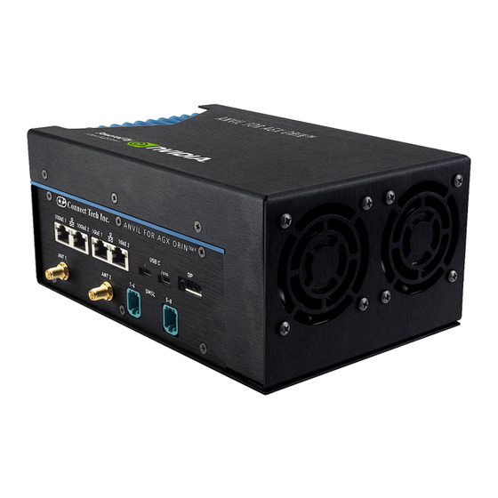
- Page 1 Anvil Embedded System CTIM-00066 Revision 0.00 2023-04-05...
-
Page 2: Table Of Contents
Connector Summary & Locations ......................... 10 External Connector Summary ........................12 Detailed Feature Description ........................13 Anvil Embedded System NVIDIA® Jetson AGX Orin™ Module Connector ..........13 Anvil Embedded System Isolated CAN Connector..................14 Power Connector ............................14 Connectors ............................14 10G Ethernet (2 Ports) ........................... - Page 3 Anvil Embedded System Users Guide www.connecttech.com System Thermal Test Results ........................25 nvfancontrol Fan Profile Setup ........................26 Mechanical Drawings & Models ........................ 27 Cables Included ............................30 Document: CTIM-00066 Page 3 of 30 Date: 2023-04-05 Revision: 0.00...
-
Page 4: Preface
The information contained within this user’s guide, including but not limited to any product specification, is subject to change without notice. Connect Tech assumes no liability for any damages incurred directly or indirectly from any technical or typographical errors or omissions contained herein or for discrepancies between the product and the user’s guide. -
Page 5: Limited Product Warranty
Connect Tech Inc. provides a one-year Warranty for this product. Should this product, in Connect Tech Inc.'s opinion, fail to be in good working order during the warranty period, Connect Tech Inc. will, at its option, repair or replace this product at no charge, provided that the product has not been subjected to abuse, misuse, accident, disaster or non-Connect Tech Inc. -
Page 6: Esd Warning
ESD Warning Electronic components and circuits are sensitive to ElectroStatic Discharge (ESD). When handling any circuit board assemblies including Connect Tech COM Express carrier assemblies, it is recommended that ESD safety precautions be observed. ESD safe best practices include, but are not limited to: •... -
Page 7: Introduction
INTRODUCTION Built to deploy massive AI workloads at the Edge, the Anvil Embedded System is the AI supercomputer guaranteed to stay cool - even at Jetson AGX Orin™ MAX-N mode. The Anvil Embedded System can withstand even the most compute intensive AI applications with its power-efficient and feature rich design. -
Page 8: Part Numbers / Ordering Information
Anvil Actively Cooled version with embedded fans ESG621-xyz* Anvil Passively Cooled version that requires user supplied external airflow *Note that various configurations exist to fill out the features of the system. For example: Adding NVMe SSDs for storage, and/or WiFi/BT and/or LTE modems. -
Page 9: Product Overview
Anvil Embedded System Users Guide www.connecttech.com PRODUCT OVERVIEW Block Diagram Document: CTIM-00066 Page 9 of 30 Date: 2023-04-05 Revision: 0.00... -
Page 10: Connector Summary & Locations
Anvil Embedded System Users Guide www.connecttech.com Connector Summary & Locations FRONT VIEW (Active Cooling) REAR VIEW (Active Cooling) Document: CTIM-00066 Page 10 of 30 Date: 2023-04-05 Revision: 0.00... - Page 11 Anvil Embedded System Users Guide www.connecttech.com FRONT VIEW (Passive Cooling) REAR VIEW (Passive Cooling) Document: CTIM-00066 Page 11 of 30 Date: 2023-04-05 Revision: 0.00...
-
Page 12: External Connector Summary
Anvil Embedded System Users Guide www.connecttech.com External Connector Summary Location External Connector Description Back PWR IN +10V to +36V Mini-Fit Jr. 6-Pin DC Power Input Connector Front DisplayPort DisplayPort ++ connector Front USB 3.2 + OTG USB 3.2 Type-C Connector (Right most USB) Front USB 3.2... -
Page 13: Detailed Feature Description
Anvil Embedded System NVIDIA® Jetson AGX Orin™ Module Connector The NVIDIA® Jetson AGX Orin™ processor and chipset are implemented on the Jetson AGX Orin™ Module. This connects to the AGX Orin module to the Anvil Embedded System via Molex Mirror Mezz 699 pin connector. -
Page 14: Anvil Embedded System Isolated Can Connector
Anvil Embedded System Users Guide www.connecttech.com Anvil Embedded System Isolated CAN Connector Power Connector Power Input: 10-36V input range Connectors Function Forge Power Supply Connector Location Type Mini Fit Jr 2x3 Right Angled Connector Part Number: 39301060 Manufacturer: Molex Mating... -
Page 15: Ethernet (2 Ports)
Anvil Embedded System Users Guide www.connecttech.com 1G Ethernet (2 Ports) Two ports of RJ45 1G BASE-T Ethernet for networking. Connectors Function GBE Network Connectivity Location Type 2x 8 pin RJ45 with integrated Magnetics Connector Manufacturer: Pulse Mating Standard RJ45 CAT 5e or better... -
Page 16: Displayport Video Output
Anvil Embedded System Users Guide www.connecttech.com DISPLAYPORT Video Output The Forge supports one DISPLAYPORT capable of 4k output resolution. Connectors Function Display Output Location Type Full size DisplayPort connector Connector Part Number: Manufacturer: Mating Standard DISPLAYPORT or DISPLAYPORT to Cable... -
Page 17: Oculink (Sff-8611) External Pcie X4 Connector
Anvil Embedded System Users Guide www.connecttech.com OCuLink (SFF-8611) External PCIe x4 Connector The Forge supports one OCuLink connector for use as an external general purpose x4 PCIe Gen 4 connection to access external peripherals. Connectors Function External OCuLink PCIe Expansion... -
Page 18: Micro Sd Card Slot
Anvil Embedded System Users Guide www.connecttech.com Micro SD Card Slot The Anvil has one micro SD cards slot. Connectors Function Memory expansion Location Type Push-Push Micro SD cards holder Connector 502570-0893 from Molex Pinout See Micro SD specification Notes Supported speed grades DS, HS, SDR12, SDR25, SDR50, SDR104, DDR50. -
Page 19: Gpio/Spi/I2C/Uarts
Anvil Embedded System Users Guide www.connecttech.com GPIO/SPI/I2C/UARTs Several General purpose I/O features are available on this interface including: 2x SPI, 2xI2C, 2xUART, 4xGPOut, 4xGPIn, 2xPWM_Out, 2xRS232/485. Connectors Function General Purpose I/O Location Type 40 pin General Purpose 3.3V I/O Connector (note: All I/O are 3.3V levels except the RS232/RS485 interfaces) - Page 20 Anvil Embedded System Users Guide www.connecttech.com GP_Out_1 GP_In_1 GP_Out_2 GP_In_2 GP_Out_3 GP_In_3 PWM_Out_0 PWM_Out_1 RS232A_TX/ RS232A_RTS/ RS485A_TXP RS485A_TXN RS232A_RX/ RS232A_CTS/ RS485A_RXP RX485A_RXN RS232B_TX/ RS232B_RTS/ RS485B_TXP RS485B_TXN RS232B_RX/ RS232B_CTS/ RS485B_RXP RS485B_RXN Notes: All I/O are 3.3V unless otherwise specified. GP_Out_x - are driven outputs and can sink or source 12mA GP_In_x - VIH (Input High Voltage minimum) = 2V.
- Page 21 Anvil Embedded System Users Guide www.connecttech.com SW Cross reference to GPIO controllers SW Interface Cross reference Connector Name Module ID Controller ID (sysfs) Connector Name SW /dev ID DTB ID GP_IN_0 GPIO01 PG.03 (386) I2C1 i2c2 i2c@c240000 GP_IN_1 GPIO04 PA.02 (350)
-
Page 22: Can Bus Interfaces
Anvil Embedded System Users Guide www.connecttech.com CAN BUS Interfaces Two non-isolated CAN Bus interfaces are available on Connectors Function CAN Bus Interface Location Type 10 pin dual CAN Bus Connector Connector Samtec TFML-05 series Mating SFSD-05-28-G-12.00SL Cable (SL or DL = Friction Lock required for locking fit) -
Page 23: Gmsl 1/2 Connector (With An Included Jcb002)
GMSL 1/2 Connector (with an included JCB002) The The Anvil Embedded System allows GMSL 1 or GMSL 2 through the Quad MATE-AX connectors. The GMSL to MIPI Deserializers are embedded on the carrier board which use 4-Lane MIPI video per 2 cameras. -
Page 24: Power Consumption & Thermals
POWER CONSUMPTION & THERMALS The Anvil Embedded System has an Operating Temperature Range of -25°C to +60°C. It is important to note that the NVIDIA® Jetson AGX Orin™ module has its own properties separate to that of the peripherals. Customer responsibility requires proper implementation of a thermal solution that maintains the Anvil Embedded System Passive cooling temperatures below the system maximums. -
Page 25: System Thermal Test Results
Anvil Embedded System Users Guide www.connecttech.com System Thermal Test Results The active cooling at full performance can meet or exceed the thermal margin requirements of the Jetson AGX Orin™ when a full system benchmark is being performed at high ambient temperatures. -
Page 26: Nvfancontrol Fan Profile Setup
Anvil Embedded System Users Guide www.connecttech.com nvfancontrol Fan Profile Setup The fan can be controlled via closed loop mode (reading temp and tach as feedback) will allow the system to adjust dynamically as setup by the user. Edit the configuration file /etc/nvfancontrol.conf with a profile that meets the dynamic needs of your system utilization and... -
Page 27: Mechanical Drawings & Models
Anvil Embedded System Users Guide www.connecttech.com MECHANICAL DRAWINGS & MODELS For a complete 3D STEP Model file of the Active Cooled Anvil Embedded System (with mounting brackets shown), please contact support@connecttech.com. Document: CTIM-00066 Page 27 of 30 Date: 2023-04-05 Revision: 0.00... - Page 28 Anvil Embedded System Users Guide www.connecttech.com For a complete 3D STEP Model file of the Passive Cooled Anvil Embedded System (with mounting brackets shown), please contact support@connecttech.com. Document: CTIM-00066 Page 28 of 30 Date: 2023-04-05 Revision: 0.00...
- Page 29 Anvil Embedded System Users Guide www.connecttech.com Included Mounting Backets: Each unit comes with rubber feet pre-installed. If required remove the rubber feet first before attaching the included mounting bracket using the supplied black 6mm M3 screws. Material of the bracket is 12GA aluminum (approx. 2mm thick).
-
Page 30: Cables Included
Anvil Embedded System Users Guide www.connecttech.com CABLES INCLUDED SFSD-20-28-G-12.00-SL (MISC connector) – 12” breakout cable with flying leads is supplied with the board purchase. SFSD-05-28-G-12.00-SL (CAN Bus) – 12” breakout cable with flying leads is supplied with the board purchase.
Need help?
Do you have a question about the Anvil and is the answer not in the manual?
Questions and answers