Advertisement
Quick Links
Chipsmall Limited consists of a professional team with an average of over 10 year of expertise in the distribution
of electronic components. Based in Hongkong, we have already established firm and mutual-benefit business
relationships with customers from,Europe,America and south Asia,supplying obsolete and hard-to-find components
to meet their specific needs.
With the principle of "Quality Parts,Customers Priority,Honest Operation,and Considerate Service",our business
mainly focus on the distribution of electronic components. Line cards we deal with include
Microchip,ALPS,ROHM,Xilinx,Pulse,ON,Everlight and Freescale. Main products comprise
IC,Modules,Potentiometer,IC Socket,Relay,Connector.Our parts cover such applications as commercial,industrial,
and automotives areas.
We are looking forward to setting up business relationship with you and hope to provide you with the best service
and solution. Let us make a better world for our industry!
Contact us
Tel: +86-755-8981 8866 Fax: +86-755-8427 6832
Email & Skype: info@chipsmall.com Web: www.chipsmall.com
Address: A1208, Overseas Decoration Building, #122 Zhenhua RD., Futian, Shenzhen, China
Advertisement

Related Manuals for Microchip Technology MRF24J40MD


Summary of Contents for Microchip Technology MRF24J40MD
- Page 1 Chipsmall Limited consists of a professional team with an average of over 10 year of expertise in the distribution of electronic components. Based in Hongkong, we have already established firm and mutual-benefit business relationships with customers from,Europe,America and south Asia,supplying obsolete and hard-to-find components to meet their specific needs.
- Page 2 Matching Circuitry, Power Amplifier, Low Noise • Data Rate: 250 kbps Amplifier • -104 dBm Typical Sensitivity with -23 dBm • PCB Antenna (MRF24J40MD), External Antenna Maximum Input Level Connector (MRF24J40ME): Ultra Miniature • +19 dBm Typical Output Power with 45 dB Tx Coaxial (U.FL), 50Ω...
- Page 3 When contacting a sales office, please specify which device, revision of silicon and data sheet (include literature number) you are using. Customer Notification System Register on our web site at www.microchip.com to receive the most current information on all of our products. Advance Information 2014 Microchip Technology Inc. DS70005173A-page 2...
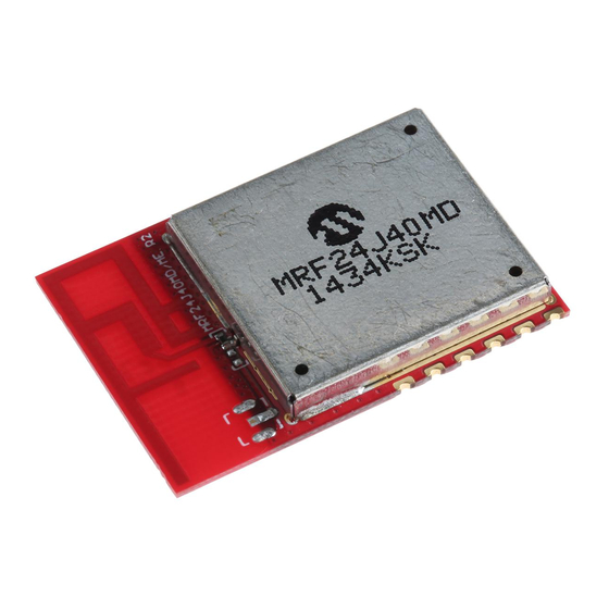
- Page 4 MRF24J40MD/ME DEVICE OVERVIEW Issue 3, December 2010): User manuals for transmitters shall display the following notice in a The MRF24J40MD/ME is a 2.4 GHz IEEE Std. conspicuous location:” for Canada. 802.15.4™ compliant, surface mount module with The MRF24J40MD/ME module is an R&TTE Directive integrated crystal, internal voltage regulator, matching assessed radio module for operation in Europe.
- Page 5 Power Power supply Ground Ground Ground Ground Legend: Pin type abbreviation: D = Digital, I = Input, O = Output FIGURE 1-2: MICROCONTROLLER TO MRF24J40MD/ME INTERFACE ® MRF24J40MD/ME INTX WAKE RESET Advance Information 2014 Microchip Technology Inc. DS70005173A-page 4...
- Page 6 • Refer to the solder paste data sheet for specific clear of metal objects. A host PCB ground plane reflow profile recommendations around the MRF24J40MD acts as a counterpoise to the PCB antenna. It is recommended to extend the • Use no-clean flux solder paste ground plane at least 0.4"...
- Page 7 0.4” 0.4” PCB Ground Plane (Counterpoise) 0.4” Underneath and extend as far as possible to the sides and below the module (at least 0.4 inches on each side) for best performance Advance Information 2014 Microchip Technology Inc. DS70005173A-page 6...
- Page 8 PA/LNA block diagram. Figure 2-5 is the schematic diagram for The MRF24J40MD/ME module is based on the the module. Microchip Technology MRF24J40 2.4 GHz IEEE The internal RF state machine is configured for the PA/ 802.15.4 RF Transceiver IC. Serial communication and LNA Mode by setting TESTMODE (0x22<2:0>) = 111.
- Page 9 To get the lowest power consumption from the 3.6.1 “RSSI Firmware Request (RSSI Mode 1)” in the MRF24J40MD/ME module during Sleep, it is neces- “MRF24J40 Data Sheet” (DS39776), perform the sary to disable the PA, PA voltage regulator and LNA.
- Page 10 Typical output power at antenna connector J1, Channel 11, 50Ω impedance. Note: Section 3.0 “Regulatory Refer Approval” for the required maximum power setting necessary to maintain certification requirements for each country the module will be used. Advance Information 2014 Microchip Technology Inc. DS70005173A-page 9...
- Page 11 MRF24J40MD/ME NOTES: Advance Information 2014 Microchip Technology Inc. DS70005173A-page 10...
- Page 12 PCB counterpoise to the PCB antenna. Additional ground trace antenna (MRF24J40MD) and 50Ω external plane on the host PCB will substantially enhance the antenna connector (MRF24J40ME).
- Page 13 Table 2-1. An antenna type comprises antennas having similar in-band and out-of-band radiation patterns. Refer to Section 3.0 “Regulatory Approval” specific regulatory requirements by country. Advance Information 2014 Microchip Technology Inc. DS70005173A-page 12...
- Page 14 2-2. between the power amplifier, U6, when transmitting and low noise amplifier, U1, when receiving. A The MRF24J40MD/ME module is based on the band-pass filter U5 is placed after the PA U6 to reduce Microchip Technology MRF24J40 IEEE 802.15.4™ 2.4 harmonics.
- Page 15 FIGURE 2-5: MRF24J40MD/ME SCHEMATIC V DD 0.01uF V DD 33pF V DD V DD V DD 18pF 18pF 33pF 470k 0.01uF 20MH z B SS84 V DD 2N7002P,215 100pF V DD i Power Net 0.01uF 0.1uF 33pF 33pF SST12LN 01 50 Ohm 4.7nH...
- Page 16 TABLE 2-2: MRF24J40MD/ME BILL OF MATERIALS Designator Quantity Value Manufacturer Manufacturer PN 33 pF Murata Electronics GRM1535C1H330JDD5D C2, C10 0.01 uF Murata Electronics GRM155R71E103KA01D C3, C6, C8, C9, C23, C25, C28, C29, C36, C43 33 pF Murata Electronics GRM1535C1H330JDD5D 100 nF...
- Page 17 TABLE 2-2: MRF24J40MD/ME BILL OF MATERIALS (CONTINUED) Designator Quantity Value Manufacturer Manufacturer PN BSS84 Fairchild Semiconductor BSS84 2N7002P,215 NXP Semiconductor 2N7002P,215 470k Yageo RC0402FR-07470KL Yageo RC0402JR-0751RL R2, R3, R4, R6, R10 0 ohm Yageo RC0402JR-070RL R7, R9 Not Populated 5.6 R...
- Page 18 MRF24J40MD/ME Printed Circuit Board FIGURE 2-8: LAYER 2 – GROUND PLANE The MRF24J40MD/ME module PCB is constructed with high temperature FR4 material, four layers and 0.032 " thick. The layers are illustrated in Figure 2-6 through Figure 2-10. The stack up of the PCB is...
- Page 19 1/2 oz. Copper Top Copper 8 mil FR4 1/2 oz. Copper Ground Plane " 0.032 12 mil FR4 " ±0.005 1/2 oz. Copper Power Plane 8 mil FR4 1/2 oz. Copper Bottom Copper Advance Information 2014 Microchip Technology Inc. DS70005173A-page 18...
- Page 20 Class B digital device, pursuant to ular Transmitter approval. Modular approval allows the part 15 of the FCC Rules. These limits are designed end user to integrate the MRF24J40MD/ME module to provide reasonable protection against harmful into a finished product without obtaining subsequent interference in a residential installation.
Need help?
Do you have a question about the MRF24J40MD and is the answer not in the manual?
Questions and answers