
Subscribe to Our Youtube Channel
Related Manuals for Toshiba MMU-UP YHP-E Series


Summary of Contents for Toshiba MMU-UP YHP-E Series
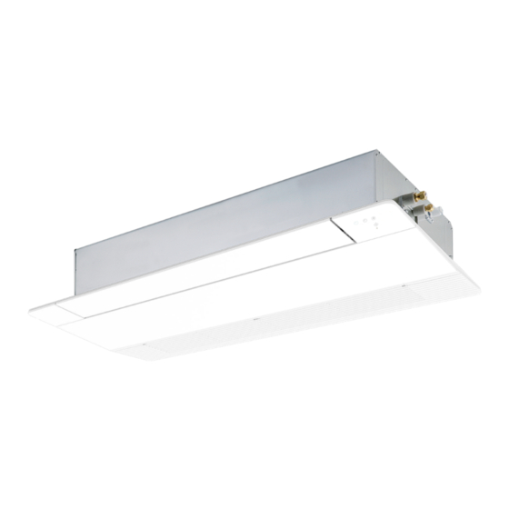
- Page 1 AIR CONDITIONER (MULTI TYPE) Installation Manual Indoor Unit For commercial use Model name: 1-Way Cassette type MMU-UP0151YHP-E MMU-UP0181YHP-E MMU-UP0241YHP-E MMU-UP0271YHP-E English...
-
Page 2: Table Of Contents
Product information of ecodesign requirements. (Regulation (EU) 2016/2281) http://ecodesign.toshiba-airconditioning.eu/en 12 Specifications ..............27 13 Notice code . - Page 3 Please read through this manual after understanding the contents below (meanings of work on the air conditioners made by Toshiba Carrier Corporation or, alternatively, he or she has indications), and be sure to follow the description.
- Page 4 – 3 – „ MEANINGS OF SYMBOLS DISPLAYED ON THE UNIT „ Warning indications on the air conditioner unit Warning indication Description This mark is for R32 refrigerant only. Refrigerant type is written on nameplate of outdoor unit. WARNING In case that refrigerant type is R32, this unit uses a flammable WARNING refrigerant.
-
Page 5: Precautions For Safety
Precautions for safety • Only a qualified installer(*1) or qualified service person(*1) is allowed to undertake work at heights using a stand of 50 cm The manufacturer shall not assume any liability for the damage or more or to remove the air inlet grille of the indoor unit to caused by not observing the description of this manual. - Page 6 – 5 – • Do not move or repair any unit by yourself. There is high voltage • Follow the instructions in the Installation Manual to install the inside the unit. You may get electric shock when removing the air conditioner. Failure to follow these instructions may cause cover and main unit.
- Page 7 • Nitrogen gas must be used for the airtight test. • Under no circumstances the power wire must not be extended. • The charge hose must be connected in such a way that it is not Connection trouble in the places where the wire is extended slack.
- Page 8 – 7 – Explanations given to user CAUTION • Upon completion of the installation work, tell the user where the This Air Conditioner has adopted a refrigerant HFC (R32 or circuit breaker is located. If the user does not know where the R410A) which does not destroy the ozone layer. circuit breaker is, he or she will not be able to turn it off in the •...
-
Page 9: Accessory Parts
Accessory parts Selection of installation place „ Accessory parts WARNING y Install the air conditioner at enough strong place to withstand the weight of the unit. Part name Q’ty Shape Usage If the strength is not enough, the unit may fall down resulting in injury. (Hand over to customers) y Install the air conditioner at a height 2.5 m or more from the floor. Installation Manual This manual (For other languages that do not appear in this Installation If you insert your hands or others directly into the unit while the air conditioner operates, it is dangerous Manual, please refer to the enclosed CD-R.) -
Page 10: Installation
– 9 – Installation „ Installation space (Unit: mm) Secure the specified space in the figure for installation and servicing. CAUTION Strictly comply with the following rules to prevent damage of the indoor units and human injury. y Do not put a heavy article on the indoor unit. (Even units are packaged) 500 mm 500 mm or more... - Page 11 „ Opening a ceiling and Treatment of ceiling Installation of ceiling opening and ‹ ‹ Hanging bolt hanging bolt Level vial The ceiling differs according to structure of building. installation of hanging bolts (levelness: 5 mm or less) For details, consult your constructor or interior finish Indoor unit contractor.
-
Page 12: Drain Piping
– 11 – Drain piping „ Installation of ceiling panel „ Wireless type (Sold separately) (Sold separately) y For length of the traversing drain pipe, restrict to CAUTION 20 m or less. Install the ceiling panel according to Installation The sensor of indoor unit with wireless remote In case of a long pipe, provide support brackets Following the Installation Manual, perform the Manual attached with it after piping / wiring work has... - Page 13 „ Connecting drain pipe „ Check the draining y Test water drain while checking the operation sound of the drain pump motor. (If the operation sound changes from continuous y Connect a hard socket (locally procured) to the hard In the test run, check that water drain is properly sound to intermittent sound, water is normally socket of the attached supplied flexible hose.
-
Page 14: Refrigerant Piping
– 13 – Refrigerant piping „ Evacuation * In case of flaring for R32 or R410A with the conventional flare tool, pull it out approx. 0.5 mm more than that for R22 to adjust to the specified flare Projection margin in flaring: B (Unit: mm) Perform vacuuming from the charge port of valve of CAUTION size. -
Page 15: Electrical Connection
Electrical connection „ Airtight test / Air purge, etc. Wrap the pipe with the attached heat insulator without any gap between the indoor unit. For airtight test, air purge, addition of refrigerant, The seam must be faced upward Indoor unit WARNING and gas leak check, refer to the Installation Manual (ceiling side). - Page 16 – 15 – „ Power supply wire and communication wires specifications <In the case of combining with outdoor units of Super Modular Multi System u series (SMMS-u)> Follow the wiring specifications in the table below even when units other than U series are mixed in the indoor units and remote controllers to be connected. Power supply wire and communication wires are locally procured. For the power supply specifications, follow to the table below.
- Page 17 „ Wire connection <In the case of combining with outdoor units other than Super Modular Multi System u series (SMMS-u)> Control wiring between indoor units, and outdoor unit (L2, L3) 1.25 mm² (Up to 1000 m) (2-core shield wire, non-polarity) Wire size : REQUIREMENT Central control line wiring (L1) 2.0 mm² (Up to 2000 m) y Be sure to connect the wires matching the terminal numbers. Incorrect connection causes a trouble. (2-core shield wire, non-polarity) y Be sure to pass the wires through the bushing of wiring connection port of the indoor unit.
-
Page 18: If U Series Models (Tu2C-Link) Are Combined With Models Other Than U Series (Tcc-Link), The Wiring
– 17 – „ Remote controller wiring „ Wiring between indoor and outdoor units Strip off approx. 9 mm the wire to be connected. NOTE Wiring diagram A wiring diagram below is an example for connection to SMMS-u series. For connecting to other outdoor unit series, refer to the Installation Manual attached to the outdoor unit to be connected. Terminal block for remote controller Terminal block... - Page 19 Applicable controls „ Installing indoor unit on high Push the menu button to make Set data ceiling ] flash. Change Set data [ with [ ] setting button. REQUIREMENT When an indoor unit is installed on a ceiling higher When the air conditioner is used for the first time, Push OFF timer button. than the standard height, make the high-ceiling setting it will take some moments after the power has By doing so, the setup is completed.
-
Page 20: Test Run
– 19 – Test run „ Change of lighting time of „ Group control filter sign In a group control, a remote controller can control up „ Before test run to maximum 8 units. According to the installation condition, the lighting time y For wiring procedure and wiring method of the of the filter sign (Notification of filter cleaning) can be y Before turning on the circuit breaker, carry out the... -
Page 21: Maintenance
Maintenance Wired remote controller Wireless remote controller ‹ (RBC-AX33UYP-E) Be sure to stop the air conditioner before making Use a vacuum cleaner to remove dust settings. CAUTION Test run (forced cooling operation) (Change the setup while the air conditioner is not from the filters or wash them with water. working.) Before maintenance, be sure to turn off the y After rinsing the air filters with water, dry them in the REQUIREMENT leakage breaker. -
Page 22: Troubleshooting
– 21 – Troubleshooting q Periodic Maintenance For environmental conservation, it is strongly recommended that the indoor and outdoor units of the air conditioner in use be cleaned and maintained regularly to ensure efficient operation of the air conditioner. When the air conditioner is operated for a long time, periodic maintenance (once a year) is recommended. If a problem occurs with the air conditioner, Furthermore, regularly check the outdoor unit for rust and scratches, and remove them or apply rustproof the OFF timer indicator alternately shows... - Page 23 Check method On the wired remote controller, central control remote controller and the interface P.C. Board of the outdoor unit (I/F), a check display LCD (Remote controller) or 7-segment display (on the outdoor interface P.C. Board) to display the operation is provided.
- Page 24 – 23 – Check code Wireless remote controller Outdoor unit 7-segment display Sensor block display of receiving unit Check code name Judging device Wired remote controller display Auxiliary code Operation Timer Ready Flash ─ TD1 sensor trouble ─ TD2 sensor trouble 01: TE1 sensor 02: TE2 sensor TE1,TE2 or TE3 sensor trouble 03: TE3 sensor 01: TL1 sensor 02: TL2 sensor...
- Page 25 Check code Wireless remote controller Outdoor unit 7-segment display Sensor block display of receiving unit Check code name Judging device Wired remote controller display Auxiliary code Operation Timer Ready Flash * : Compressor 1 side Compressor trouble (Step out) * : Compressor 2 side ─ TD3 sensor miswiring ─ ─...
- Page 26 – 25 – Check code Wireless remote controller Outdoor unit 7-segment display Sensor block display of receiving unit Check code name Judging device Wired remote controller display Auxiliary code Operation Timer Ready Flash Detected indoor unit address Indoor unit overflow trouble Indoor unit ─ Outdoor heat exchanger freezing trouble ─...
- Page 27 *1 Inverter quantity information (SMMS-e, SMMS-7, SMMS-u, SMMS∞, SHRM-A) Compressor Inverter Inverter Trouble Compressor 1 Compressor 2 Compressor 1 + Compressor 2 Fan1 Compressor 1 + Fan1 Compressor 2 + Fan1 Compressor 1 + Compressor 2 + Fan1 Fan2 Compressor 1 + Fan2 Compressor 2 + Fan2 Compressor 1 + Compressor 2 + Fan2 Fan1 + Fan2 Compressor 1 + Fan1 + Fan2...
-
Page 28: Specifications
– 27 – Specifications Notice code y Notice code is a function only in TC2U-Link communication. Sound power level (dBA) Weight (kg) Model y When the outdoor or indoor unit detects its conditions requiring caution or maintenance, this function notices you Main unit (Ceiling panel) Cooling Heating to check your units with the spanner mark (Notice code mark) on the wired remote controller or central controller... - Page 29 Declaration of Conformity Declaration of Conformity Manufacturer: TOSHIBA CARRIER (THAILAND) CO., LTD. Manufacturer: TOSHIBA CARRIER (THAILAND) CO., LTD. 144 / 9 Moo 5, Bangkadi Industrial Park, Tivanon Road, Tambol Bangkadi, 144 / 9 Moo 5, Bangkadi Industrial Park, Tivanon Road, Tambol Bangkadi,...
- Page 30 – 29 – Warnings on Refrigerant Leakage ▼ NOTE 2 The standards for minimum room volume are as follows. 1) No partition (shaded portion) Check of Concentration Limit The room in which the air conditioner is to be installed requires a design that in the event of refrigerant gas leaking out, its concentration will not exceed a set limit. Refrigerant R32 The refrigerant R32 which is used in the air conditioner is mildly flammable. In Europe and areas where IEC standards apply, EN/IEC 60335-2-40 is the applicable standard.
- Page 31 59-EN 60-EN – 30 –...
-
Page 32: Appendix
– 31 – Appendix Work instructions 5. When a commercially available dryer is attached to Existing pipes: Cannot be used. the existing pipes. Are there scratches or dents on the existing pipes? The existing R22 and R410A piping can be reused for y Use new pipes. - Page 33 144 / 9 Moo 5, Bangkadi Industrial Park, Tivanon Road, Tambol Bangkadi, Amphur Muang, Pathumthani 12000, Thailand 1131450101-1...
Need help?
Do you have a question about the MMU-UP YHP-E Series and is the answer not in the manual?
Questions and answers