Baccara G75-DFC - Differential Filtration Controller Manual
- Installation operation & maintenance (16 pages)
Advertisement
- 1 Getting Started
- 2 Parts Identification
- 3 Wires connections - DC
- 4 Installation instructions
- 5 "Dryconn" #22 to #12 AWG
- 6 Operating Modes
- 7 Factory Setting
- 8 Programmable Setting
- 9 Maintenance
- 10 Seal Replacement
- 11 Troubleshooting
- 12 Flow Chart for G75-DFC Differential Filtration Controller
- 13 Documents / Resources
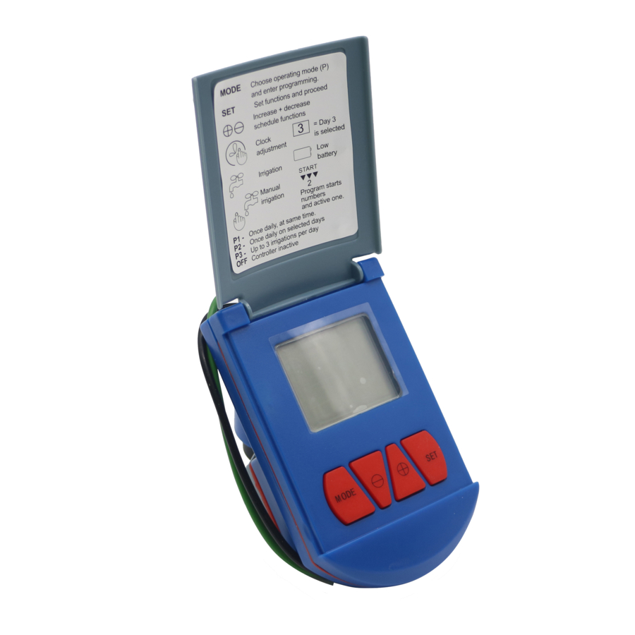
Getting Started
Description
The Baccara Differential Filtration Controller combines a Controller and Differential Pressure Sensor (DP).
Molded DP with three wires cable. Controller with seven wires for valves and sensor interface.
The DFC controller is offered as DC Latch only, and it is suitable for Baccara solenoid Latch 4 ohm.
The controllers operates up to three solenoids. The Controller shows the actual DIF pressure and the pressure SET point. The Flushing Cycle (FC) begins when DIF≥SET appears.
Display
The LCD display shows:
- Actual DIF pressure
- SET point pressure
- FC counter
- Faucet icon displayed whilst FC operating
- Low battery icon appears when battery needs replacing.
Mechanical
- Operating temperature -10ºC to + 60ºC
- Dust and water tight: IP66
- UV protection
- Max. High pressure 14bar/200psi
Electrical
- Power supply: DC unit - 9V battery
- Internal memory retains settings when power supply disconnected.
Mounting
DP: 2"/52mm diameter
2 ft/60 cm. 3 wires cable
High and low pressure ports 1/8"
BSP/NPT male
High pressure port marked on housing.

Connect High pressure before Low pressure. Disconnect Low pressure before High pressure.
Parts Identification

Wires connections - DC

Installation instructions
LV9000 - Wire connectors

- Strip wires ¾" and group bare wires ends together. No pre-twisting necessary with solid wire. Pre-twist stranded wire. If using both wire types, wrap stranded wire around solid wires. See 1A.
- Insert wires through flexible sealing fingers and bend wires wires into either <V- Channel>.
- Push inner sleeve into pre-filled outer sleeve until double-locked. Pre-filled silicone fuller waterproofs the connection. Do not reuse connector.
"Dryconn" #22 to #12 AWG

- Strip wires 13 mm.
- Align frayed strands or conductors.
- Do not pre-twist. Place stripped wires with ends even, lead stranded wires slightly.
- Twist connector onto wires pushing firmly until hand-tight. DO NOT over torque.
- Swipe excess sealant in and around conductors.
DO NOT REUSE.
Operating Modes
- Auto
- Off
- FC counter rest
- Manual FC
UD = Upper Digits
LD = Lower Digits
Auto
This mode is the running mode of the controller.
UD shows counter value (see section 3). LD shows DIF and SET values.
Whilst in FC, the faucet icon will turn on and the operating valve number will blink.
Battery icon will blink when low battery is detected: 
Display will turn OFF (blank) one minute after no button is pressed (shut off).
Display will turn on with pressing any button.
If DIF≥SET for (n) consecutive measuring samples, FC starts. FC ends one min. after the last valve shut down.
Off
This mode is for OFF season or to stop Auto Mode permanently.
LD shows OFF.
No pressure measuring process occurs Display will shut off as in Auto Mode.
Press MODE shortly (0.5 sec.) to shift the controller Mode from Auto to OFF or backwards.
FC Counter reset
- From Auto Mode press MODE and
![]() together UD will blink with counter content.
together UD will blink with counter content. - For RESET, press MODE and
![]() together, UD shows c000, then back to Auto.
together, UD shows c000, then back to Auto. - If RESET is not needed, press SET, then back to Auto.
 together UD will blink with counter content.
 together, UD shows c000, then back to Auto.
Manual FC
- From Auto Mode press SET and
![]() together, FC starts.
together, FC starts.
Display shows "Hand" and "Faucet" icons. VALVE and operating valve # blink. - When FC is completed the MODE returns to Auto.
- To stop Manual FC press SET and
![]() together, FC will stop and return to Auto.
together, FC will stop and return to Auto.
 together, FC will stop and return to Auto.
Factory Setting
These settings cannot be programmed by the user:
- Pressure units: bar
- FC delay: 2 consecutive readings of DIF≥SET before FC starts.
- Sample Interval time: Auto, as the DIF becomes closer to the SET point, the interval time between samples shortens.
Max. Interval 60 secs./Min. Interval 5 sec. - Off time between valves during FC: 20 sec.
- Consecutive FC count number for alarm: 5 count
- Sensor calibration.
Programmable Setting
Valve on Time
Default: 40 sec. range (5 min. 59 sec.) Same time for all valves.
- To set Valve on Time press MODE until below display appears:
![]()
- Use
![]() and
and ![]() to adjust seconds.
to adjust seconds. - Press SET to continue.
- Use
![]() and
and ![]() to adjust minutes.
to adjust minutes. - Press SET to complete setting.

 and
and  and
and Interval time between FC
Default: A
This interval value will be the max. time between two consecutive FC if DIF pressure does not execute FC.
Range (23 hrs: 59 min. A)
If A is selected, this setting is ignored.
- To set Interval Time between FC press MODE (one long press), then one short press. The below display appears:
![]()
- Use
![]() and
and ![]() to adjust minutes. (If A is selected, press SET to complete this setting).
to adjust minutes. (If A is selected, press SET to complete this setting). - Press SET to continue.
- Use
![]() and
and ![]() to adjust hours.
to adjust hours. - Press SET to complete this setting.

 and
and Select Valve no.
Default: Valve #1 (Max. three valves)
You have a choice of which # valve will be operated by the controller.
In case of output #1 burnout, you can connect the valve to output #2 and select valve #2 to operate or #3.
- To select the valve #. Press MODE (one long press, then two short presses. This display appears:
![]()
- Use
![]() to select valve #1. Valve #1 remain valve #2 blinks. Or use
to select valve #1. Valve #1 remain valve #2 blinks. Or use ![]() to deselect valve #1. Valve #1 disappears, valve #2 blinks.
to deselect valve #1. Valve #1 disappears, valve #2 blinks. - Repeat the above for valves 2 and 3.

Maintenance
Battery Installation
Replace the battery at the start of each irrigation season and when the low battery symbol appears.
Use a 9V alkaline top quality battery only.
- Using a Phillips screw driver, remove the four battery cover screws.
- Remove the battery cover and seal.
- Replace the battery.
- After reattaching the seal, put the cover back, and secure with the four screws.
Seal Replacement

Troubleshooting
| Problem | Cause | Solution |
| No FC occurrence | No water | Open water |
| Battery dead | Replace battery | |
| Off Mode | Set Auto Mode | |
| Valve does not work | Valve # select is incorrect | #Correct valve select |
| Shut Off | Press any button | |
| Sleep | Press MODE | |
| Blank display | Battery dead | Replace battery |
Flow Chart for G75-DFC Differential Filtration Controller


Documents / ResourcesDownload manual
Here you can download full pdf version of manual, it may contain additional safety instructions, warranty information, FCC rules, etc.
Download Baccara G75-DFC - Differential Filtration Controller Manual
Advertisement


Need help?
Do you have a question about the G75-DFC and is the answer not in the manual?
Questions and answers