
Related Manuals for CommScope MRx18


Summary of Contents for CommScope MRx18
- Page 1 MRx18/x18 & MRx18/x18/x18 & MRx18/y18/y18 & MRx18/y18 miniRepeater Dual- / Triple-Segment Dual-Band User's Manual M0139ACN...
- Page 2 DISCLAIMER: This document has been developed by CommScope, and is intended for the use of its customers and customer support personnel. The information in this document is subject to change without notice. While every effort has been made to eliminate errors, CommScope disclaims liability for any difficulties arising from the interpretation of the information contained herein.
-
Page 3: Table Of Contents
5.3. STATUS BAR 5.4. STATUS 5.5. SETTINGS 5.5.1. Settings - Radio Frequency 5.5.2. Settings - Alarms 5.5.3. Settings - Modem Control 5.5.4. Settings - LAN Connectivity 5.5.5. Settings - User Account M0139ACN Manual for MRx18 Dual/Triple-Segment & Dual-Band Page 3... - Page 4 ELECTRICAL SPECIFICATIONS MRX18 8.1.1. MRx18/x18 Dual-Segment/MRx18/x18/x18 Triple-Segment 8.1.2. MRx18/y18/y18 and MRx18/y18 Dual-Band 8.2. ENVIRONMENTAL AND SAFETY SPECIFICATIONS MRX18 8.3. MECHANICAL SPECIFICATIONS MRX18 8.4. SPARE PARTS LIST 9. LIST OF CHANGES 10. INDEX Page 4 M0139ACN Manual for MRx18 Dual/Triple-Segment & Dual-Band...
- Page 5 Figures and Tables FIGURES AND TABLES figure 3-1 Block diagram MRx18/x18 dual-segment (e.g. MR918/918) ....16 figure 3-2 Block diagram MRx18/x18/x18 triple-segment (e.g. MR918/918/918) ..16 figure 3-3 Block diagram MRx18/y18 dual-band (e.g. MR2118/918) ......17 figure 3-4 Block diagram MRx18/y18/y18 dual-band (e.g. MR2118/918/918) ..17 figure 3-5 Connectors of MRx18 ................
-
Page 6: General
Caution: High frequency radiation in operation. Risk of health hazards associated with radiation from the antenna(s) connected to the unit. Implement prevention measures to avoid the possibility of very close proximity to the antenna(s) while in operation. Page 6 M0139ACN Manual for MRx18 Dual/Triple-Segment & Dual-Band... -
Page 7: Property Damage Warnings
Unless otherwise agreed to in writing by CommScope, CommScope’s general limited product warranty (http://www.commscope.com/Resources/Warranties/) shall be the warranty governing the MRx18 Units, including the installation, maintenance, usage and operation of the MRx18 Units. -
Page 8: Compliance
FCC data base, is not exceeded. The industrial boosters are shipped only as a naked booster without any installation devices or antennas as it needs for professional installation. Page 8 M0139ACN Manual for MRx18 Dual/Triple-Segment & Dual-Band... - Page 9 émetteur. Les utilisateurs et les installateurs doivent être fournis avec des instructions d’installation de l’antenne et des conditions de fonctionnement de l’émetteur pour satisfaire la conformité aux expositions M0139ACN Manual for MRx18 Dual/Triple-Segment & Dual-Band Page 9...
- Page 10 9. Note: This unit complies with European standard EN60950-1 / EN62368-1. Page 10 M0139ACN Manual for MRx18 Dual/Triple-Segment & Dual-Band...
- Page 11 Country specific information about collection and recycling arrangements per the Waste Electrical and Electronic Equipment (WEEE) Directive and implementing regulations is available on CommScope’s website. http://www.commscope.com/About-Us/Corporate-Responsibility-and-Sustainability/Environment/#recycling M0139ACN Manual for MRx18 Dual/Triple-Segment & Dual-Band Page 11...
-
Page 12: About Commscope
For technical assistance and support, please also contact the local office or CommScope directly at one of the addresses listed in the following chapter. Page 12 M0139ACN Manual for MRx18 Dual/Triple-Segment & Dual-Band... -
Page 13: Contacting Commscope
Please register for an account if you don’t have one. Once you have access, click to select a product line link to access the documentation for that product. 1.6.3. Technical Training To access the CommScope University Training site, please use the following web address http://www.commscopeuniversity.com or scan the QR code to the right. -
Page 14: Introduction
The opportunity to adjust the passband of a repeater helps to cover any specific segment or frequency band. Due to modular design, the single-varia version MRx18 may be available as a dual- / triple-varia segment or a dual-band-varia version in one cabinet. The dual- / triple- segment MRx18/x18(/x18) is able to transmit two or three variable segments within one frequency band. - Page 15 • RSSI and status indication via display • Optional remote control via SMS • Connection to LAN • Remote alarming through SNMP alarm traps • Compliant with all regulatory agencies (e.g. GSM 05.05, 3GPP and FCC) M0139ACN Manual for MRx18 Dual/Triple-Segment & Dual-Band Page 15...
-
Page 16: Functional Description
3. Functional Description 3.1. General The name of a specific MRx18 miniRepeater reflects the frequency range in which it operates (e.g. MR918 => 900 MHz frequency range). The operation principle of the dual- and triple-segment is depicted in the following two block diagrams: E0783B8 figure 3-1 Block diagram MRx18/x18 dual-segment (e.g. -
Page 17: Figure 3-3 Block Diagram Mrx18/Y18 Dual-Band (E.g. Mr2118/918)
3. Functional Description The MRx18 dual-band operates in two different frequency bands: The first illustration shows the MRx18/y18 dual-band – one segment per each frequency band: E0783BB figure 3-3 Block diagram MRx18/y18 dual-band (e.g. MR2118/918) The second illustration shows the MRx18/y18/y18 dual-band – one segment in... -
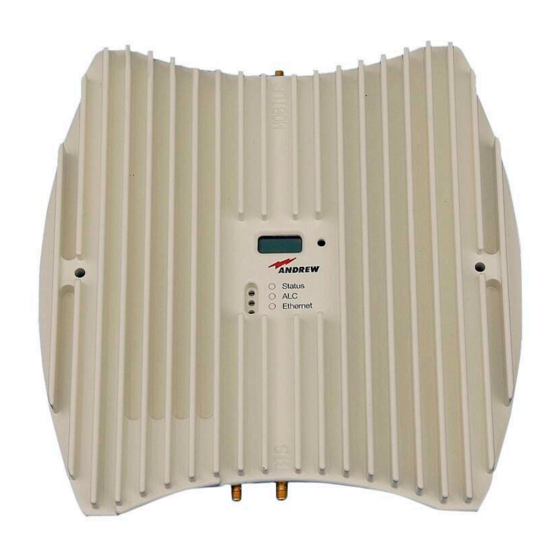
Page 18: Design And Connectors
3-5 Connectors of MRx18 Note: SMA connectors have a specified torque of 0.45 N-m. Use an appropriate tool to fasten and unfasten these connectors. Do not over-tighten the connectors or screws. Page 18 M0139ACN Manual for MRx18 Dual/Triple-Segment & Dual-Band... -
Page 19: Installation And Commissioning
3. Notice: Use proper mounting hardware depending on the structure of e.g. the wall where the unit will be installed. To mount the MRx18 to a wall, proceed as follows: MRx18 miniRepater Wall-mounting bracket 1. Use two appropriate screws... -
Page 20: Electrical Installation
2 M5x50 screws 2. Insert the MRx18 into the wall-mounting bracket. 3. Fasten the repeater by means of 2 metric M5x50 fillister-head screws to the two thread nuts of the wall mounting bracket. figure 4-2 Wall mounting procedure 4.2. -
Page 21: Figure 4-3 Power Connection Of Dc Connector With Mrx18
4-3 Power connection of DC connector with MRx18 Align the donor antenna towards the BTS. The MRx18 provides antenna alignment assistance. Therefore, press the "Reset and installation assistance" switch (see chapter 3.2 Design and Connectors) for at least four seconds after (!) the boot process has been finished (i.e. - Page 22 For local connection, connect the straight CAT 6 patch cable to the Ethernet connector of the MRx18 and the network connector of a laptop or PC. For MRx18 connection to a LAN network connect the cross-over cable. (Note: The MRx18 operates at 10 Mbps and full-duplex).
- Page 23 (Ethernet LED starts blinking). It is not possible to execute a reset when a local connection is established. Browser mode settings for IE11: Open the „Compatibility View Settings“ and mark all checkboxes: M0139ACN Manual for MRx18 Dual/Triple-Segment & Dual-Band Page 23...
-
Page 24: Software Setup
Enter User name: MRx18 Enter Password: MRx18 Please note that passwords are case-sensitive when entering "MRx18". Click the button. If an incorrect username or password has been entered, an error message appears. This message prompts to insert your username or password anew. Press key F5 to refresh the login mask. -
Page 25: Status Bar
These data is being read out of the MRx18 repeater. Unit Displays the unit location of the MRx18 repeater - user defined area entered in Location chapter 5.5.3 Settings - Modem Control or 5.5.4 Settings - LAN Connectivity. - Page 26 Restart repeater. If the error persists, contact Alarm within the defined range. technical support. Tempera- Temperature too high Check installation location of MRx18 and ture (>80°C) improve ventilation. table 5-5 Status - Alarms Page 26 M0139ACN Manual for MRx18 Dual/Triple-Segment & Dual-Band...
-
Page 27: Settings
After a disconnection without Logout or a timeout of the session, changes in these tabs will not be applied. 5.5.1. Settings - Radio Frequency figure 5-5 Settings - Radio Frequency M0139ACN Manual for MRx18 Dual/Triple-Segment & Dual-Band Page 27... - Page 28 Band Depending on the repeater model, the respective bands equipped are displayed. To power on, check "Power ON Band MRx18". Uncheck "Power ON Band MRx18" to power down the RF-section of the respective band. The band that is powered Power down is not visible in the Settings page.
- Page 29 ETSI refers to the standards meeting <-36 dBm or <-30 dBm Intermodulation products. For output power values outside the scale marked with ETSI, the intermodulation products are <-13 dBm. table 5-7 Radio Frequency – General M0139ACN Manual for MRx18 Dual/Triple-Segment & Dual-Band Page 29...
- Page 30 GSM900 and UMTS900, are transmitted on a separate frequency segment allocated in one frequency band. When Auto Gain is disabled, these parameters cannot be accessed. table 5-8 Radio Frequency - Auto Gain Page 30 M0139ACN Manual for MRx18 Dual/Triple-Segment & Dual-Band...
-
Page 31: Settings - Alarms
The severity of alarms may be: Current Alarm Local Oscillator disabled, warning, minor, major, critical Temperature table 5-9 Settings - Alarms 5.5.3. Settings - Modem Control figure 5-7 Settings - Modem Control M0139ACN Manual for MRx18 Dual/Triple-Segment & Dual-Band Page 31... - Page 32 A.I.M.O.S. table 5-10 Settings - Modem Control To make the changes valid, the Apply button has to be pressed and the user has to log out. Page 32 M0139ACN Manual for MRx18 Dual/Triple-Segment & Dual-Band...
-
Page 33: Settings - Lan Connectivity
IP address. Max. 15 characters are allowed for the Net Bios Name. To make the changes valid, the Apply button has to be pressed and the user has to log out. M0139ACN Manual for MRx18 Dual/Triple-Segment & Dual-Band Page 33... - Page 34 When DHCP is enabled no entries can be made. table 5-12 LAN Connectivity - DHCP Settings To make the changes valid, the Apply button has to be pressed and the user has to log out. Page 34 M0139ACN Manual for MRx18 Dual/Triple-Segment & Dual-Band...
-
Page 35: Settings - User Account
The new password has to be repeated. Repeat Password table 5-14 Settings - User Account To make the changes valid, the Apply button has to be pressed and the user has to log out. M0139ACN Manual for MRx18 Dual/Triple-Segment & Dual-Band Page 35... -
Page 36: Maintenance
The software version of the modem connected to the repeater is shown. If no Software modem is connected or the modem cannot be recognized, the message "no Version valid modem found" appears. table 5-15 Maintenance - Modem Debugging Page 36 M0139ACN Manual for MRx18 Dual/Triple-Segment & Dual-Band... -
Page 37: Logout
Logout is possible from the Status, Settings, and Maintenance pages at any time. Note: Settings made in LAN Connectivity and User Account will only become valid after the user has executed a manual logout. M0139ACN Manual for MRx18 Dual/Triple-Segment & Dual-Band Page 37... -
Page 38: Upload New Software Version
5-12 Upload new software version Provide power to the MRx18 and press the return button of the laptop or PC during the boot process (i.e. red ALC LED is blinking for four seconds). After the software upload, the MRx18 will reboot automatically. - Page 39 SW has to be updated to V3.0.0 and the automation tool has to be executed before uploading a newer SW version. For detailed instructions, the SW Release Note of MRx18 SW V3.0.0 shall be observed. Malfunction of EEPROM might be indicated by: ○...
-
Page 40: Optional Equipment
6. Optional Equipment 6.1. External Modem (Kit) As an option, the MRx18 can also be equipped with an external modem for remote supervision. Besides alarm forwarding via SMS (including heartbeat), settings of the MRx18 can be changed remotely via A.I.M.O.S. or by a mobile by sending SMS commands. -
Page 41: Alarming And Supervision
7-1 Display and alarm LEDs 7.1. Alarm LEDs Color Indication If the LED is off, the respective MRx18 does not receive any DC power. A green light indicates the normal operation of the repeater. Green Power is present and the current consumption of the unit is within the specifications. -
Page 42: Display And Reset & Installation Assistance Button
Functions of the Reset Button: To align the donor antenna of the MRx18 towards the BTS via the antenna alignment assistance (as described in chapter 4.2 Electrical Installation), press the "Reset and installation assistance" switch (illustrated in figure above) for at least four seconds after (!) the boot process has been finished (i.e. -
Page 43: Figure 7-3 Display - Rssi
In alarm condition the display shows* the segment and kind of alarm; when more than one alarm in different segments is raised the display changes alternately between the active alarms. When the MRx18 is in normal operation with no active alarms, "System Ok" is indicated. -
Page 44: Appendix
8.1.1. MRx18/x18 Dual-Segment/MRx18/x18/x18 Triple-Segment The electrical specifications of the MRx18 miniRepeater are basically identical to the ones of the MRx18 single-band (see separate manual, which can be downloaded as well). Deviations are stated in the following: Existing dual- / triple-segment versions *:... -
Page 45: Mrx18/Y18/Y18 And Mrx18/Y18 Dual-Band
8. Appendix 8.1.2. MRx18/y18/y18 and MRx18/y18 Dual-Band The electrical specifications of the dual MRx18 are basically identical to the ones of the MRx18 single-band. Deviations are stated in the following table. Existing combinations below carry one variable segment in the basic cabinet and up to two variable segments in the extension cabinet. -
Page 46: Environmental And Safety Specifications Mrx18
Height, width, depth 240 x 240 x 70 mm (9.5 x 9.5 x 2.8 in) Weight 3.0 kg (6.6 lb) All data is subject to change without notice. figure 8-1 Cabinet drawing MRx18/x18/x18 Page 46 M0139ACN Manual for MRx18 Dual/Triple-Segment & Dual-Band... -
Page 47: Spare Parts List
Antenna 824-960 1710-2500 7579858 RF Cable-Kit SMA to N 500 mm 7594320 Modem-Kit EGS5-3 MRX18 * 7721516 Modem-Kit PHS8 MRx18 7679560 * This kit is the successor of Modem-Kit EGS5 MRx18 (7615377). M0139ACN Manual for MRx18 Dual/Triple-Segment & Dual-Band Page 47... -
Page 48: List Of Changes
PSU Kit AC IN 100-240 V / OUT 6 V 60 W ZA 7565921 Last Replaceable Unit (LRU) is the entire miniRepeater MRx18 listed above, except for the manual, the power supply kits and the optional equipment (antennas, RF cable kit and modem kits) listed above. -
Page 49: Index
System Overview ..........14 IP Address ............22 Troubleshooting ............ 26 LAN Connectivity ........33, 34, 35 LEDs ..............41 Login ..............37 Logout ............24, 37 Upload Software ........... 38 Maintenance ............36 M0139ACN Manual for MRx18 Dual/Triple-Segment & Dual-Band Page 49...
Need help?
Do you have a question about the MRx18 and is the answer not in the manual?
Questions and answers