Table of Contents
Advertisement
Quick Links
Advertisement
Table of Contents

Related Manuals for CommScope MRx18


Summary of Contents for CommScope MRx18
- Page 1 MRx18 miniRepeater Release 2 Single-Band User's Manual M0139ADY...
- Page 2 DISCLAIMER: This document has been developed by CommScope, and is intended for the use of its customers and customer support personnel. The information in this document is subject to change without notice. While every effort has been made to eliminate errors, CommScope disclaims liability for any difficulties arising from the interpretation of the information contained herein.
-
Page 3: Table Of Contents
STATUS BAR 5.4. STATUS 5.5. SETTINGS 5.5.1. Settings – Radio Frequency 5.5.2. Settings – Alarms 5.5.3. Settings – Modem Control 5.5.4. Settings – LAN Connectivity 5.5.5. Settings – User Account M0139ADY User’s Manual for MRx18 Rel. 2 Single-Band Page 3... - Page 4 DISPLAY AND RESET & INSTALLATION ASSISTANCE BUTTON 8. APPENDIX 8.1. ELECTRICAL SPECIFICATIONS MRX18 8.2. ENVIRONMENTAL AND SAFETY SPECIFICATIONS MRX18 8.3. MECHANICAL SPECIFICATIONS MRX18 8.4. SPARE PARTS LIST 9. LIST OF CHANGES 10. INDEX Page 4 M0139ADY User’s Manual for MRx18 Rel. 2 Single-Band...
- Page 5 3-1 Block diagram ................... 15 figure 3-2 Connectors of MRx18 ................16 figure 4-1 MRx18, position of screws for wall mounting ..........17 Figure 4-2 Power connection of DC connector with MRx18 ........19 figure 5-1 Login page ....................22 figure 5-2 Status-bar ....................
-
Page 6: General
Development User Equipment Canada; formerly IC / Industry Uplink Canada UMTS Universal Mobile Telecommunication System Light Emitting Diode Uninterruptable Power Supply Local Maintenance Terminal Uniform Resource Locator Low Noise Amplifier Page 6 M0139ADY User’s Manual for MRx18 Rel. 2 Single-Band... -
Page 7: Health And Safety
Unless otherwise agreed to in writing by CommScope, CommScope’s general limited product warranty (http://www.commscope.com/Resources/Warranties/) shall be the warranty governing the MRx18 Units, including the installation, maintenance, usage and operation of the MRx18 Units. -
Page 8: Compliance
FCC data base, is not exceeded. The industrial boosters are shipped only as a naked booster without any installation devices or antennas as it needs for professional installation. Page 8 M0139ADY User’s Manual for MRx18 Rel. 2 Single-Band... - Page 9 Overvoltage Category may comply with ANSI/IEEE C62.11, CSA Certification Notice No. 516, CSA C22.2 No. 1, or UL 1449. Suitability of the component for the application shall be determined for the intended installation. M0139ADY User’s Manual for MRx18 Rel. 2 Single-Band Page 9...
- Page 10 9. Note: This unit complies with European standard EN60950-1 / EN62368-1. Page 10 M0139ADY User’s Manual for MRx18 Rel. 2 Single-Band...
- Page 11 Country specific information about collection and recycling arrangements per the Waste Electrical and Electronic Equipment (WEEE) Directive and implementing regulations is available on CommScope’s website. http://www.commscope.com/About-Us/Corporate-Responsibility-and-Sustainability/Environment/#recycling M0139ADY User’s Manual for MRx18 Rel. 2 Single-Band Page 11...
-
Page 12: About Commscope
1. General 1.5. About CommScope CommScope is the foremost supplier of one-stop, end-to-end radio frequency (RF) solutions. Part of the CommScope portfolio are complete solutions for wireless infrastructure from top-of-the-tower base station antennas to cable systems and cabinets, RF site solutions, signal distribution, and network optimization. For patents see www.cs-pat.com. -
Page 13: Contacting Commscope
Please register for an account if you don’t have one. Once you have access, click to select a product line link to access the documentation for that product. 1.6.3. Technical Training To access the CommScope University Training site, please use the following web address http://www.commscopeuniversity.com or scan the QR code to the right. -
Page 14: Introduction
The possibility to adjust the passband of a repeater helps to cover any specific segment or frequency band. Due to modular design the single varia version MRx18 may be available as a triple- varia segment or a dual-band-varia version in one cabinet. Auto Gain functionality enables automatic gain adjustment in order to maximize performance;... -
Page 15: Functional Description
• Complying with all regulatory agencies (GSM 05.05, 3GPP and FCC) 3. Functional Description 3.1. General The name of a specific MRx18 miniRepeater reflects the frequency range in which it operates (e.g. MR918 => 900 MHz frequency range). The operation principle is depicted in the following block diagram:... -
Page 16: Design And Connectors
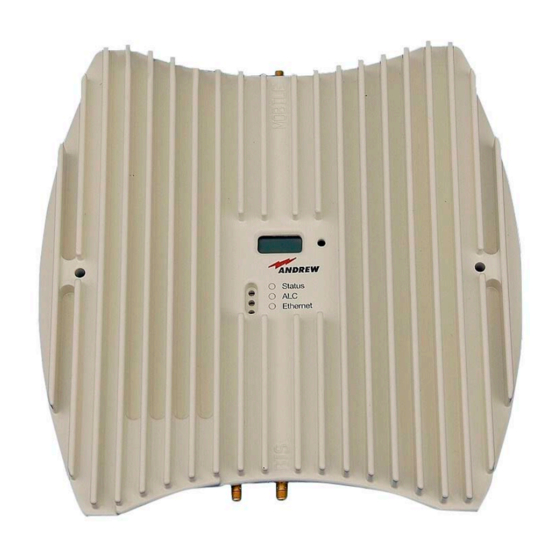
3-2 Connectors of MRx18 Note: SMA connectors have a specified torque of 0.45 Nm. Use an appropriate tool to fasten and unfasten these connectors. Do not over-tighten the connectors or screws. Page 16 M0139ADY User’s Manual for MRx18 Rel. 2 Single-Band... -
Page 17: Installation And Commissioning
Mount the MRx18 to a wall with two Position of screws screws (spacers not required): figure 4-1 MRx18, position of screws for wall mounting M0139ADY User’s Manual for MRx18 Rel. 2 Single-Band Page 17... -
Page 18: Electrical Installation
Connect the antenna cables to the antenna connectors and the antennas. Use only the power supply delivered with the unit. Do not modify the power supply unit (PSU) and cable. Do not mount the PSU to the ceiling. Page 18 M0139ADY User’s Manual for MRx18 Rel. 2 Single-Band... -
Page 19: Figure 4-2 Power Connection Of Dc Connector With Mrx18
Figure 4-2 Power connection of DC connector with MRx18 Align the donor antenna towards the BTS. The MRx18 provides antenna alignment assistance. Therefore, press the “Reset and installation assistance” switch (see chapter 3.2 Design and Connectors) for at least ten seconds after (!) the boot process has been finished (i.e. - Page 20 For local connection, connect the straight CAT 6 patch cable to the Ethernet connector of the MRx18 and the network connector of a laptop or PC. For MRx18 connection to a LAN network, connect the cross-over cable. (Note: The MRx18 operates at 10 Mbps and full-duplex).
- Page 21 (Ethernet LED starts blinking). It is not possible to execute a reset when a local connection is established. Browser mode settings for IE11: Open the „Compatibility View Settings“ and mark all checkboxes: M0139ADY User’s Manual for MRx18 Rel. 2 Single-Band Page 21...
-
Page 22: Software Setup
This message prompts to insert your username or password anew. Press key F5 to refresh the login mask. If an incorrect username or password has been entered for three times, the interface to the repeater is locked for 30 minutes. Page 22 M0139ADY User’s Manual for MRx18 Rel. 2 Single-Band... -
Page 23: Menu Bar - Buttons
5.3. Status Bar figure 5-2 Status-bar The status bar is located on the bottom of each webpage. The following information is displayed: These data is being read out of the MRx18 repeater. Designation Description Displays the unit location of the MRx18 repeater – user defined area Unit Location entered in chapter 5.5.3 Settings –... -
Page 24: Status
In the Status page, actual values are shown. The values are referenced to the condition when the status page has been opened. Furthermore, present alarms of the MRx18 are listed in this page. No values/alarms are captured in case the RF section is switched off (see chapter 5.5.1). -
Page 25: Settings
Settings – User Account require a logout by the user to make the changes valid. After a disconnection without Logout or a timeout of the session, changes in these tabs will not be applied. M0139ADY User’s Manual for MRx18 Rel. 2 Single-Band Page 25... -
Page 26: Settings - Radio Frequency
Radio Frequency - Description of Power Parameters Band For the single band repeater MRx18 only one band is displayed. To power on, check “Power ON Band MRx18”. Uncheck “Power ON Band Power MRx18” to power down the RF-section of the repeater. - Page 27 Radio Frequency - Description of General Parameters Band For the single band repeater MRx18 only one band is displayed. Enter the DL frequency range to be amplified (start and stop frequency) within the duplexer range that is indicated above the field.
-
Page 28: Settings - Alarms
5. Software Setup Radio Frequency - Description of Auto Gain Parameters Band For the single band repeater MRx18 only one band is displayed. UL/DL When Auto Gain is enabled, the gain is adjusted automatically. With an entry in Imbalan the Auto Gain imbalance field, the UL gain is decreased compared to the DL gain ce (dB) for this value. -
Page 29: Settings - Modem Control
This field is read-only. System ID With integration in A.I.M.O.S. a configuration SMS is sent from A.I.M.O.S. that overwrites the entries of these fields by the entries coming from A.I.M.O.S. M0139ADY User’s Manual for MRx18 Rel. 2 Single-Band Page 29... -
Page 30: Settings - Lan Connectivity
To make the changes valid, the Apply button has to be pressed and the user has to log out. 5.5.4. Settings – LAN Connectivity figure 5-7 Settings – LAN Connectivity Page 30 M0139ADY User’s Manual for MRx18 Rel. 2 Single-Band... - Page 31 * Note: When DHCP is enabled no entries can be made. Table 5-12 LAN Connectivity – DHCP Settings To make the changes valid, the Apply button has to be pressed and the user has to log out. M0139ADY User’s Manual for MRx18 Rel. 2 Single-Band Page 31...
-
Page 32: Settings - User Account
The new password has to be repeated. Repeat Password table 5-14 Settings – User Account To make the changes valid, the Apply button has to be pressed and the user has to log out. Page 32 M0139ADY User’s Manual for MRx18 Rel. 2 Single-Band... -
Page 33: Maintenance
The software version of the modem connected to the repeater is shown. If no Software modem is connected or the modem cannot be recognized, the message “no Version valid modem found” appears. Table 5-15 Maintenance – Modem Debugging M0139ADY User’s Manual for MRx18 Rel. 2 Single-Band Page 33... -
Page 34: Logout
Logout is possible from the Status, Settings, and Maintenance pages at any time. Note: Settings made in LAN Connectivity and User Account will only become valid after the user has executed a manual logout. Page 34 M0139ADY User’s Manual for MRx18 Rel. 2 Single-Band... -
Page 35: Upload New Software Version
192.168.1.2 PUT “C:\Temp\MRx18Vxxx.hex” (Do not press return button yet). figure 5-11 Upload new software version 5. Provide power to the MRx18 and press the return button of the laptop or PC during the boot process (i.e. red ALC LED is blinking for four seconds). - Page 36 SW has to be updated to V3.0.0 and the automation tool has to be executed before uploading a newer SW version. For detailed instructions, the SW Release Note of MRx18 SW V3.0.0 shall be observed. Malfunction of EEPROM might be indicated by: ○...
-
Page 37: Optional Equipment
6. Optional Equipment 6.1. External Modem (Kit) As an option, the MRx18 can be also equipped with an external modem for remote supervision. Besides alarm forwarding via SMS (including heartbeat), settings of the MRx18 can be changed remotely via A.I.M.O.S. or by a mobile by sending SMS commands. -
Page 38: Alarming And Supervision
LO cannot lock and the repeater Orange might not work properly. If the LED is off, the respective MRx18 does not receive any DC power. Status A red light indicates the temperature alarm, which switches to power-down mode once an over-temperature has been reached. -
Page 39: Display And Reset & Installation Assistance Button
Functions of the Reset Button: To align the donor antenna of the MRx18 towards the BTS via the antenna alignment assistance (as described in chapter 4.2 Electrical Installation), press the “Reset and installation assistance” switch (illustrated in figure above) for at least ten seconds after (!) the boot process has been finished (i.e. -
Page 40: Figure 7-3 Display - Rssi
In alarm condition the display shows* the segment and kind of alarm. When the MRx18 is in normal operation with no active alarms, “System Ok” is indicated. When the display is in sleep mode it has to be activated by the “Reset and installation assistance button”, first. -
Page 41: Appendix
Recommended bandwidth for UMTS carriers: 1 carrier: 4.6 MHz, 2 carriers: 9.6 MHz, 3 carriers: 14.6 MHz MRx18 extended power versions: +24 dBm @ 1 carrier, +21 dBm @ 2 carriers meeting <-13 dBm intermodulation products Not considering power supply losses All data is subject to change without notice. - Page 42 Recommended bandwidth for UMTS carriers: 1 carrier: 4.6 MHz, 2 carriers: 9.6 MHz, 3 carriers: 14.6 MHz MRx18 extended power versions: +24 dBm @ 1 carrier, +21 dBm @ 2 carriers meeting <-13 dBm intermodulation products Not considering power supply losses All data is subject to change without notice.
- Page 43 Recommended bandwidth for UMTS carriers: 1 carrier: 4.6 MHz, 2 carriers: 9.6 MHz, 3 carriers: 14.6 MHz MRx18 extended power versions: +24 dBm @ 1 carrier, +21 dBm @ 2 carriers meeting <-13 dBm intermodulation products Not considering power supply losses All data is subject to change without notice.
- Page 44 This power reduction is to be made by means of input power or gain reduction and not by an attenuator at the output of the device. Not considering power supply losses All data is subject to change without notice. Page 44 M0139ADY User’s Manual for MRx18 Rel. 2 Single-Band...
- Page 45 This power reduction is to be made by means of input power or gain reduction and not by an attenuator at the output of the device. Not considering power supply losses All data is subject to change without notice. M0139ADY User’s Manual for MRx18 Rel. 2 Single-Band Page 45...
- Page 46 This power reduction is to be made by means of input power or gain reduction and not by an attenuator at the output of the device. Not considering power supply losses All data is subject to change without notice. Page 46 M0139ADY User’s Manual for MRx18 Rel. 2 Single-Band...
- Page 47 For certain passband adjustments and carrier constellations the limits for unwanted emissions for protection of base station receiver might require slight restrictions Not considering power supply losses All data is subject to change without notice. M0139ADY User’s Manual for MRx18 Rel. 2 Single-Band Page 47...
-
Page 48: Environmental And Safety Specifications Mrx18
For further details, please refer to the “Environmental and Safety Specifications” leaflet of the supplier. Operating temperature range +5° C to +40° C Ingress protection IP30 All data is subject to change without notice. Page 48 M0139ADY User’s Manual for MRx18 Rel. 2 Single-Band... -
Page 49: Mechanical Specifications Mrx18
MR1818U 7600606 MR1918 7613702 MR2118 7618228 MR2618* 7633937 * In case MR2618 is equipped with a modem kit, 60W power supply kit is recommended (see parts list in the following). M0139ADY User’s Manual for MRx18 Rel. 2 Single-Band Page 49... -
Page 50: List Of Changes
7679560 * This kit is the successor of Modem-Kit EGS5 MRx18 (7615377). Last Replaceable Unit (LRU) is the entire miniRepeater MRx18 listed above, except for the power supply kits and the optional equipment (antennas, RF cable kit, and modem kits) listed above. -
Page 51: Index
Troubleshooting ............ 25 Maintenance, Modem Debugging ......33 Menu Bar .............. 23 Web-based Browser ..........22 Modem (External) ..........37 Webpage Update ..........34 Modem Control ............. 28 Modem Debugging ..........33 M0139ADY User’s Manual for MRx18 Rel. 2 Single-Band Page 51...
Need help?
Do you have a question about the MRx18 and is the answer not in the manual?
Questions and answers