Table of Contents
Advertisement
Quick Links
Advertisement
Table of Contents

Related Manuals for LightwaveRF LW107


Summary of Contents for LightwaveRF LW107
- Page 1 PIR Sensor Instruction manual LW107 Professional Series www.lightwaverf.com...
- Page 2 EN 55022: 2010, EN 61000-3-2: 2006 +A1: 2009 +A2: 2009 Class A, EN 61000-3-3: 2008, EN61000-4-2: 2009, EN 61000-4-3: 2006 +A1: 2008 +A2: 2010, EN 61000-4-4: 2012, EN 61000-4-5: 2006, EN 61000-4-6: 2009, EN 61000-4-11: 2004 For and on behalf of LightwaveRF PLC ---------------------------------------- Name J Shermer...
-
Page 3: How Do I Get Started
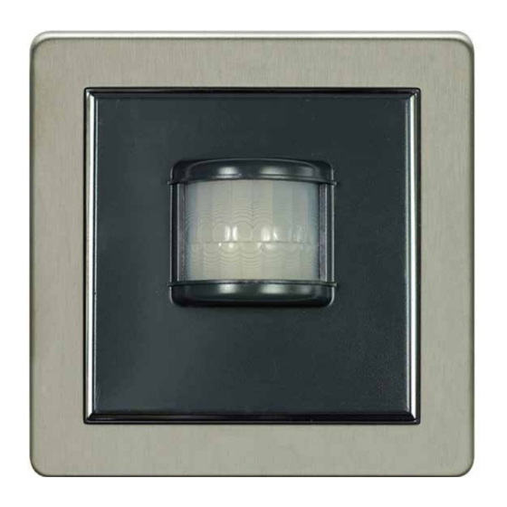
How does it work? The PIR will trigger a LightwaveRF device when it senses movement. It can be positioned anywhere (indoors). To install it, you will need simply to apply the adhesive strips provided and attach the PIR to a wall or flat surface. - Page 4 Installation Overview Metal surround Main sensor lens (lens cover not shown) Main unit IMPORTANT: Please retain these instructions for guidance on how to link other LightwaveRF receivers. For additional guidance please visit www.lightwaverf.com...
-
Page 5: Installation
NOTE: It is important to install this product in accordance with the following instructions. Failure to do so may void your warranty. LightwaveRF is fully legal to install in your own home. However, if in doubt, always consult a qualified electrician. - Page 6 Installation Inserting/replacing batteries & accessing sliders To insert or replace the batteries, the main PIR unit must be removed from the base section. Removing the main unit from the base will also allow access to the rear sliders (which change the PIR settings) without having to detach the base from the wall once the PIR has been attached.
- Page 7 Installation Insert the screwdriver under the tab situated at the bottom of the main unit as shown. Gently remove the main unit from the base. The battery compartment is located on the rear of the main unit. Two AAA batteries are required to power the unit.
- Page 8 Installation Setting the detection angle Setting the detection angle will determine the area in which the presence of movement will trigger the PIR. This angle can be altered by adding the lens covers that partially cover the sensor lens. Vertically, the maximum detection angle is always 65 degrees.
- Page 9 Installation Wall mounting the PIR The PIR is designed to be wall mounted (although it can be positioned anywhere indoors) using the adhesive strips provided or suitable screws. NOTE: Before permanently mounting the PIR, it is important to ensure that the location is suitable for the nature of the operation required and that the unit is setup and working as desired.
-
Page 10: Device Setup
The PIR sensor will trigger any LightwaveRF receiver, such as a dimmer switch or a power socket, to which it is ‘linked’. It is possible to link a PIR to as many LightwaveRF devices as desired as long as they are within its range (approx. 10-15m indoors under normal conditions). - Page 11 Device setup Unlinking the PIR from a LightwaveRF device Place the LightwaveRF device that you wish to remove in ‘linking’ mode. For information on how to do this please refer to the instruction manual for that specific LightwaveRF device. Whilst the LightwaveRF device is in linking mode, move the slider marked ‘learn’...
-
Page 12: Setting The Light Sensitivity
Device setup Setting the ‘o ’ command delay If the learn slider is set to ‘1/0’, then an ‘o ’ command will be sent to a linked Lightwa- veRF device after the initial ‘on’ command sent by the PIR. The period of time between these two commands can be customised using the ‘Time delay’... -
Page 13: Battery Low Indicator
PIR to acclimatise to the new light setting. Finalising setup Once the PIR has been linked to its target LightwaveRF devices and the settings adjusted, it can be mounted in its final position. Once in position, it is important to allow at least 30 seconds for the PIR to acclimatise to the light level in its new environment. - Page 14 LightwaveRF dimmer or plug-in at night. If the kids get up to use the bathroom in the middle of the night, the sensor will be triggered and the hall light and bathroom can be set to automatically light up.
-
Page 15: Troubleshooting
If the problem persists, try moving the PIR closer to the socket, or consider using a LightwaveRF Signal Booster to extend the range by relaying the signal between the PIR and target device. - Page 16 Solution: Is there an automatic time delay set on the PIR? If so, even though the linked LightwaveRF devices have been turned o manually, the PIR will still be waiting to send an ‘o ’ command. It will not turn on any devices again...
- Page 17 A red light in the sensor lens will flash after the PIR has sent a command. Can I control multiple devices with one PIR? Yes, you can link as many LightwaveRF receiver devices (such as dimmers and sockets) as you wish to the same PIR.
-
Page 18: Technical Specification
Technical Specification Specification RF frequency: 433.92 MHz Output rating: 3V Batteries: 2x AAA Mounting: Standard single back-box, sticky pads or screw to wall Dimensions: Width 88mm, Height 88mm, Depth 27mm Warranty: 2 year standard warranty... - Page 19 Innovation Campus Birmingham Faraday Wharf Holt Street Birmingham B7 4BB www.lightwaverf.com Version 2.3...
Need help?
Do you have a question about the LW107 and is the answer not in the manual?
Questions and answers