Advertisement
Introduction
The Control4® IO Extender V2 enables a Control4 system to control home theaters, video devices, garage doors, motion sensors, and other devices that use infrared (IR), serial, contact, and relay connections. The IO Extender serves well as the companion to the EA Series of entertainment and automation controllers to expand input and output capabilities of a Control4 system.
The IO Extender V2 adds the ability to power the device by PoE+ to simplify installation and provide power and network connectivity over a single CAT5e/CAT6 network cable.
In addition, the IO Extender V2 provides flexible options for mounting in an equipment rack (1U) or on a shelf. The included rack ears may be installed at the front or back of the IO Extender V2 for maximum installation flexibility.
Box contents
The following items are included in the box:
- IO Extender V2 (C4-IOXV2)
- AC power cord
- IR emitters (8)
- Warranty card
- Rack ears (2)
- Four-position terminal blocks for contacts and relays (4)
Accessories sold separately
- Control4 Gigabit PoE+ Injector (AC-POE2-B)
- Pakedge Managed Gigabit Switch with 8 Rear Facing PoE+/PoE Ports (SX-8P)
- Pakedge 24 Port Managed Switch with 24 PoE or 12 PoE+ Ports (SX-24P)
Warnings

To reduce the risk of electrical shock, do not expose this apparatus to rain or moisture.

In an over-current condition on contact output the software disables the output. If the attached contact sensor does not appear to power on, remove the device from the controller.
If this product is used as a means to open and close a garage door, gate, or similar device, use safety or other sensors to ensure safe function. Follow appropriate regulatory and safety standards governing project design and installation. Failure to do so may result in property damage or personal injury.
Requirements and specifications
 Note: The Ethernet network should be installed before you install the IO Extender.
- Composer Pro is required to configure this device. See the Composer Pro User Guide (ctrl4.co/cpro-ug) for details.
- The IO Extender V2 requires Control4 OS 2.9 or newer.
Specifications
| Model number | C4-IOXV2 |
| Network | |
| Ethernet | 10/100BaseT compatible |
| Inputs / Outputs | |
| IR OUT | 8 IR out—5V 27mA max output |
| SERIAL OUT | 4 DB9 ports |
| Contact | 8 contact sensors—30VDC maximum input 12VDC 1.25A maximum output |
| Relay | 8 relays—AC: 36V, 2A; DC: 24V, 2A maximum |
| Power | |
| Power requirements | 100-240 VAC, 60/50 Hz or PoE+—up to 25.5W, IEEE 802.3at-2009 |
| Power consumption | Max: 30W, 102 BTUs/hour Idle: 10W, 34 BTUs/hour |
| Other | |
| Operating temperature | 32˚ ~ 104˚F (0˚ ~ 40˚C) |
| Storage temperature | 4˚ ~ 158˚F (-20˚ ~ 70˚C) |
| Dimensions (H x W x D) | 17.5" (444 mm) x 10.125" (258 mm) x 1.875" (49 mm) w/feet |
| Mounting | 1U rack mount with included rack ears |
| Weight | 6.55 lbs (2.97 kg) |
| Shipping weight | 9.60 lbs (4.35 kg) |
Additional resources
The following resources are available for more support:
- Control4 Knowledgebase ( kb.control4.com) and Dealer Forums (forums.control4.com)
- Control4 Technical Support
- Control4 website (www.control4.com)
- Composer Pro documentation in online help or PDF format available on the Dealer Portal under Resources ( ctrl4.co/docs)
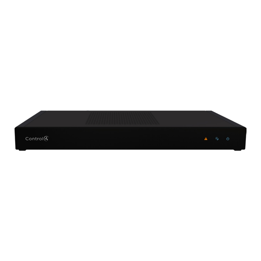
Front view

- Data LED —The Data LED turns red when an over-current condition on the contact outputs is detected.
- Status LED —The Status LED flashes blue during the boot process
![information]() Note: The Status LED flashes orange during the factory restore process. See "Resetting to factory settings" in this document.
Note: The Status LED flashes orange during the factory restore process. See "Resetting to factory settings" in this document. - Link LED —The blue LED indicates that the IO Extender has been identified in the project and is communicating with Director.
- Power LED —The blue LED indicates that power is connected. The IO Extender turns on immediately after power is applied to it.
Back view

- Power plug port —AC power receptacle for an IEC 60320-C13 power cord.
- SERIAL — Four DB9 serial ports for RS-232 control. See "Connecting the serial ports" in this document.
- ID—ID button to identify the device in Composer Pro.
- IR—Eight 3.5 mm jacks for up to eight IR emitters. See "Setting up IR emitters" in this document for more information.
- ETHERNET — RJ-45 jack for a 10/100BaseT Ethernet connection. The IO Extender can be powered over Ethernet with a PoE+ connection.
- LEDs — Rear LEDs that mirror the status of the LEDs on the front.
- FACTORY RESET —Factory reset button to restore the IO Extender to factory defaults. See "Resetting to factory settings"
- Contact/Relay port —Connect up to eight relay devices and eight contact sensor devices to the terminal block connector. Relay connections are COM, NC (normally closed), and NO (normally open). Contact sensor connections are +12, SIG (signal), and GND (ground).
Installing the IO Extender
To install the IO Extender:
- Ensure that the home network is in place before starting system setup. The IO Extender requires a network connection to use all of the features as designed.
- Mount the extender in a rack or stacked on a shelf. Always allow plenty of ventilation. See "Mounting the IO Extender in a rack" in this document.
- Connect system devices. Attach IR, serial, contact, and relay devices as described in "Connecting the serial ports," "Connecting the contact ports," "Connecting the relay ports," and "Setting up IR emitters."
- Connect the controller to the network. Connect an Ethernet patch cable to the RJ-45 port and to the network port on the wall or at the network switch.
![information]() Note: If powering the IO Extender with a PoE+ connection, we recommend that you connect any external devices (serial, IR, contacts, and relays) first, before powering up the IO Extender with the Ethernet PoE connection.
Note: If powering the IO Extender with a PoE+ connection, we recommend that you connect any external devices (serial, IR, contacts, and relays) first, before powering up the IO Extender with the Ethernet PoE connection. - Power up the IO Extender. Connect the power cord to the extender's power plug port (or connect the Ethernet cable if powering over PoE+) and then into an electrical outlet.
![information]() Note: If powering the IO Extender with AC power, we recommend that you connect any external devices (serial, IR, contacts, and relays) first, before powering up the IO Extender.
Note: If powering the IO Extender with AC power, we recommend that you connect any external devices (serial, IR, contacts, and relays) first, before powering up the IO Extender.
Mounting the IO Extender in a rack
Using the included rack ears, the IO Extender can easily be mounted in a rack for convenient installation and flexible rack placement.
To attach the rack ears to the IO Extender:
- Remove the two screws in each of the rubber feet on the bottom of the extender.
- Remove the rubber feet and place the rack ears. The rack ears can be positioned for front or rear rack mounting.
- Use the screws from the rubber feet to secure the rack ears to the extender.
Connecting the serial ports
The IO Extender provides four DB9 serial ports. The serial ports support many different baud rates (acceptable range: 1200 to 115200 baud for odd and even parity).
- To configure a port's serial settings, connect the driver's RS-232 connection to the IO Extender serial port in the Connections tab in Composer Pro.
Connecting the driver to the serial port will apply the serial settings contained in the driver file to the serial port. See the Composer Pro User Guide (ctrl4.co/cpro-ug) for details.
Setting up IR emitters
The IO Extender provides eight IR ports. Your system may contain thirdparty products that are controlled through IR commands. The included IR emitters can send commands from the controller to any IR-controlled device.
- Connect one of the included IR emitters into an IR OUT port on the IO Extender.
- Remove the adhesive backing from the emitter (round) end of the IR receiver and affix it to the device to be controlled over the IR receiver on the device.
Pluggable terminal block connectors
For the contact and relay ports, the IO Extender makes use of a pluggable terminal block connector, which is a removable plastic part that locks in individual wires (included).
To connect a device to the pluggable terminal block:
- Remove the terminal block from the back of the IO Extender.
![information]() Note: The COM, NC, and NO terminals are used for relay devices (outputs or something to control). The +12 , SIG, and GND terminals are used for contact devices (inputs and sensors).
Note: The COM, NC, and NO terminals are used for relay devices (outputs or something to control). The +12 , SIG, and GND terminals are used for contact devices (inputs and sensors). - Insert the wires into the appropriate holes and secure the wires by tightening the screws.
- After securing all of the wires in the terminal block, re-insert it into the appropriate slot in the IO Extender.
![information]() Note: The upper and lower terminal blocks are not interchangeable.
Note: The upper and lower terminal blocks are not interchangeable.
Connecting the contact ports
The IO Extender provides eight contact ports for the included pluggable terminal blocks. See Figures 3-5 for examples on how to connect common devices to the contact port.

Figure 3. Connecting a dry contact (door sensor)

Figure 4. Connecting a contact that requires power (motion sensor)

Figure 5. Connecting a doorbell to the contact
Connecting the relay ports
The IO Extender provides eight relay ports for the included pluggable terminal block. With most applications, attach one wire to the COM terminal and the other to the NO or NC terminal. The relay switch closes or opens when the relay is activated.
See Figures 6-9 to learn how to connect a device to the relay port.

Figure 6. Connecting a relay device, normally open (fireplace)

Figure 7. Connecting a relay device that needs 12V (power amplifier)

Figure 8. Connecting both a contact and a relay (garage door)

Figure 9. Connecting a dual-relay device (blinds)
Composer Pro driver information
Use Auto Discovery and SDDP to add the driver to the Composer project. See the Composer Pro User Guide for details.
Troubleshooting

Resetting to factory settings
The factory restore process will restore any system settings and software back to factory state.
To restore the IO Extender to the factory default image:
- Disconnect power from the IO Extender.
- Insert a straightened paper clip into the hole labeled FACTORY RESET on the back of the IO Extender.
- Reconnect power power to the IO Extender and continue to hold the FACTORY RESET button.
- Continue to hold the button for about five to seven seconds until the Status LED rapidly blinks orange. After the Status LED blinks rapidly, release the button and the factory restore process will begin.
Resetting the network settings
To reset the controller network settings to default:
- Disconnect power from the IO Extender.
- While pressing and holding the ID button on the back of the IO Extender, reconnect power to the controller.
- Hold the ID button until the Data, Link, and Power LEDs are solid blue, then immediately release the button.
- If the Status LED stays orange during the boot sequence, press and hold the ID button until the Status LED blinks blue, and then release it.
LED status information

Regulatory/Safety information
To review regulatory information for your Control4 products, see the information located on the Control4 website at ctrl4.co/reg.
Warranty
Visit ctrl4.co/warranty for details.
More help
For the latest version of this document and to view additional materials, open the URL below or scan the QR code on a device that can view PDFs.
MOST RECENT VERSION
ctrl4.co/ioxv2-ig

MORE INFO ON EA CONTROLLERS
ctrl4.co/ea

control4.com | 888.400.4070
Copyright ©2021, Snap One, LLC. All rights reserved. Snap One and its respective logos are registered trademarks or trademarks of Snap One, LLC (formerly known as Wirepath Home Systems, LLC), in the United States and/or other countries. Control4, SnapAV, and Wirepath are also registered trademarks or trademarks of Snap One, LLC. Other names and brands may be claimed as the property of their respective owners. Snap One makes no claim that the information contained herein covers all installation scenarios and contingencies, or product use risks. Information within this specification subject to change without notice.

Documents / Resources
References
http://ctrl4.co/cpro-ug
![kb.control4.com]() Dealer Portal
Dealer Portalhttp://forums.control4.com
Control4 Smart Homes
![ctrl4.co]() Dealer Portal
Dealer PortalRegulatory Documentation
![ctrl4.co]() Snap One
Snap Onehttp://ctrl4.co/ioxv2-ig
http://ctrl4.co/ea
Control4 Smart Homes
Download manual
Here you can download full pdf version of manual, it may contain additional safety instructions, warranty information, FCC rules, etc.
Download Control4 IO Extender V2 C4-IOXV2 Installation Guide
Advertisement


Need help?
Do you have a question about the IO Extender V2 C4-IOXV2 and is the answer not in the manual?
Questions and answers