Table of Contents
Advertisement
Quick Links
Wireless Contact / Relay
Extender Installation Guide
Features
The Wireless Contact/Relay Extender is intended for use as a device you
®
can control with your Control4
system. It is for the user who is looking for
ways to control contact or relay devices in areas away from the main
controller or who is simply looking for additional contacts and/or relays.
When installed, the Contact/Relay Extender is physically connected to up to
four contacts and/or four relays and communicates to the Control4 system
using either an Ethernet connection or a ZigBee (wireless) connection.
The Contact/Relay Extender is designed to sit on a standard rack shelf rather
than be mounted with traditional rack ears. Its approximate dimensions are
6.5" wide (1/2 RU) x 1.5" tall (just under 1 RU) x 7.0" deep and it comes with
a small plastic rack that enables you to store it in a vertical position.
WARNING! To reduce the risk of serious injury or death, turn all
power OFF before installing this product.
WARNING! Do NOT use this device to control a non-dimmable load.
WARNING! This product generates heat. The device must be
operated within specified operating temperature limits.
Using this product in a manner other than outlined in this document
voids your warranty. Further, Control4 is NOT liable for any damage
incurred with the misuse of this product. See "Limited 1 Year
Warranty."
Requirements
Models:
CXM-RCR1-B Wireless Contact / Relay Extender
(802.15.4)
Power:
_____VAC 50/60 Hz
_____W
Communications:
ZigBee (802.15.4)
10/100 Ethernet
Specifications
?
?
?
Control4 Wireless Contact / Relay Extender Installation Guide
What's in the Box
•
Control4 Wireless Contact/Relay Extender
•
AC power cord (2-prong)
•
Vertical Mount Bracket
•
Wireless Contact / Relay Extender Installation Guide (this guide)
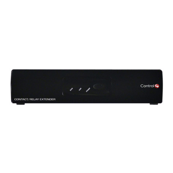
About the Hardware
Front Panel
The front panel of the Contact/Relay Extender has three red LEDs indicating
power and network connection status for Ethernet and ZigBee. A small
button on the front panel enables you to identify the unit to the network
during setup.
....and it acts as a "reset" when pressed for 10 seconds.
[Reset not currently supported...Should it be?]
1
2
1. Ethernet LED:
•
Flashing = Searching for an Ethernet link
•
On = Ethernet link established
2. ZigBee LED:
•
Flashing = Searching for a ZigBee link
•
On = ZigBee link established
3. Power LED:
•
On = Power present
4. ID Button:
•
When appropriate during system setup, press to uniquely identify this Contact/
Relay Extender to the network. Or, when a reset is needed, press and hold
for 10 seconds. [Reset not currently supported...Should it be?]
Back Panel
Become familiar with the back panel of the Wireless Contact/Relay Extender.
1
2
1. Power plug port—For supplied power cord only.
2. Contacts 1-4—Plugable Terminal Block connector for up to four dry con-
tact closure, or logic input connections, such as door switches or motion
sensors.
3. Relays 1-4—Plugable Terminal Block connector for up to four normally
closed or normally opened switchable connections, such as blinds, fire-
place, or projector screens.
4. Ethernet—RJ-45 for a 10/100 Ethernet connection.
3
4
3
4
1
Advertisement
Table of Contents

Related Manuals for Control 4 CXM-RCR1-B


Summary of Contents for Control 4 CXM-RCR1-B
- Page 1 See “Limited 1 Year Warranty.” Requirements Models: CXM-RCR1-B Wireless Contact / Relay Extender 1. Power plug port—For supplied power cord only. (802.15.4) 2. Contacts 1-4—Plugable Terminal Block connector for up to four dry con-...
- Page 2 Installation Instructions Regulatory Compliance Ensure that the location and intended use meet the following This product complies with standards established by the following regulatory criteria: bodies: • Install in accordance with all national and local electrical codes. • Federal Communications Commission (FCC) •...
Need help?
Do you have a question about the CXM-RCR1-B and is the answer not in the manual?
Questions and answers