Table of Contents
Advertisement
Quick Links
Wireless
Contact / Relay Extender
Installation Guide
Features.
The Wireless Contact/Relay Extender is intended for use with your Control4
system. This product addresses the need for additional or remotely located
contacts and relays.
The Contact/Relay Extender includes four contact-sensing inputs and four
normally-open or normally-closed relays. The Contact/Relay Extender
communicates to the Control4 system using either an Ethernet connection or
a ZigBee wireless (IEEE 802.15.4) connection.
The Contact/Relay Extender is designed to be installed using any of three
methods: (1) free-standing on a horizontal surface, (2) vertical-standing
using the included mounting base, or (3) surface-mounted using the built-in
screw mounts.
Specifications
Models:
CXM-RCR1-B Wireless Contact / Relay Extender
Power:
120 V~, 60/50 Hz, 14 W
Communications:
Wireless: ZigBee mesh networking (802.15.4)
Wired: 10/100 Ethernet
Dimensions:
Width = 7.10"
Height = 1.68"
Depth = 6.5"
Weight:
24 oz. with mounting base
22 oz. without mounting base
What's in the Box
•
Control4 Contact/Relay Extender
•
AC power cord (2-prong)
•
Vertical Mounting Base
•
Two 12-conductor plug-in terminal blocks
•
Wireless Contact / Relay Extender Installation Guide (this guide)
IMPORTANT! Using this product in a manner other than outlined in
this document voids your warranty. Further, Control4 is NOT liable for
any damage incurred with the misuse of this product. See "Limited 1
Year Warranty."
WARNING! Important Safety Information
CAUTION! TO REDUCE THE RISK OF ELECTRICAL SHOCK, DO
NOT OPEN THE CHASSIS. NO USER-SERVICEABLE PARTS
INSIDE. REFER SERVICING TO QUALIFIED SERVICE
PERSONNEL.
1. Do not use this apparatus near water.
2. Clean only with dry cloth.
3. Do not block any ventilation openings. Install in accordance with the man-
ufacturer's instructions.
4. Do not install near any heat sources such as radiators, heat registers,
stoves, or other apparatus (including amplifiers) that product heat.
5. Protect the power cord from being walked on or pinched particularly at
®
plugs, convenience receptacles, and the point where they exit from the
apparatus.
6. Only use attachments/accessories specified by the manufacturer.
7. Use only with the cart, stand, tripod, bracket, or table specified by the
manufacturer, or sold with the apparatus. When a cart is used, use cau-
tion when moving the cart/apparatus combination to avoid injury from tip-
over.
8. Unplug this apparatus during lighting storms or when unsued for long
periods of time.
9. Refer all servicing to qualified service personnel. Servicing is required
when the apparatus has been damaged in any way, such as power-sup-
ply cord or plug is damaged, liquid has been spilled or objects have fallen
into the apparatus, the apparatus has been exposed to rain or moisture,
does not operate normally, or has been dropped.
WARNING! Do not expose the apparatus to dripping or splashing.
Do not place objects filled with liquids near the apparatus.
WARNING! To reduce the risk of fire or electrical shock, do not
expose this apparatus to rain or moisture.
About the Hardware
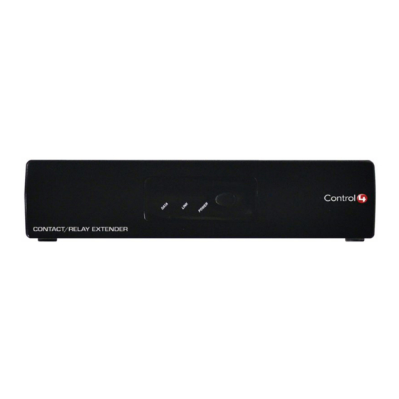
Front Panel
The front panel interface includes an ID button for identifying the unit on the
network, and LEDs to indicate power and communication status.
1. DATA LED: On = Ethernet link established
2. LINK LED: On = ZigBee link established
3. POWER LED: On = Power present
4. ID Button: When prompted by the Composer software during setup, press
this button to uniquely identify this Contact/Relay Extender to the network.
1
2
3
4
Advertisement
Table of Contents

Related Manuals for Control 4 CXM-RCR1-B


Summary of Contents for Control 4 CXM-RCR1-B
- Page 1 WARNING! Do not expose the apparatus to dripping or splashing. Do not place objects filled with liquids near the apparatus. Models: CXM-RCR1-B Wireless Contact / Relay Extender WARNING! To reduce the risk of fire or electrical shock, do not Power: 120 V~, 60/50 Hz, 14 W expose this apparatus to rain or moisture.
- Page 2 Back Panel Test to see if it is working properly: Control any of the system contact and relay devices that you connected to the Contact/Relay Extender in the extended location. You can use the many different interfaces available in a Control4 system (Remote Controls, Keypads, Touch Screens, or the On-Screen GUI) to control devices attached to the Contact/Relay Extender.
Need help?
Do you have a question about the CXM-RCR1-B and is the answer not in the manual?
Questions and answers