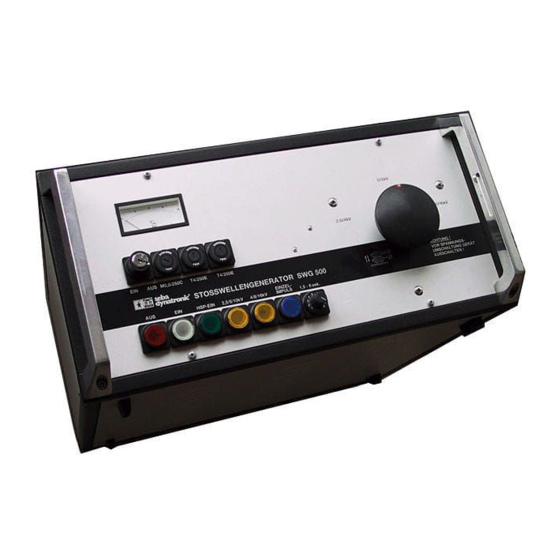
Summary of Contents for Megger SWG 500
- Page 1 Operating Manual SHOCK DISCHARGE GENERATOR Produktbild wie in den Prospekten ohne Rahmen SWG 500 Ansprechpartner Frau Badziura Issue: 02 (10/2017) – EN 128312842...
- Page 3 Megger have before-hand declared their consent in writing. The content of this handbook is subject to change without notice. Megger cannot be made liable for technical or printing errors or shortcomings of this handbook. Megger also disclaim all responsibility for damage resulting...
- Page 4 Terms of Warranty Megger accept responsibility for a claim under warranty brought forward by a customer for a product sold by Megger under the terms stated below. Megger warrant that at the time of delivery Megger products are free from manufacturing or material defects which might considerably reduce their value or usability.
-
Page 6: Table Of Contents
Contents Description General Technical data Design Current supply Putting into operation Safety Earthing of the instrument Connection to the faulty cable Isolation of open cable ends Selection of the surge voltage Safety terms as per VDE 0104 2.6.1 Ready for mains connection 2.6.2 Ready for operation 2.6.3... -
Page 7: Description
FLE 66 or FLE 90, and then indicated acoustically and/or optically IMPORTANT: The SWG 500 is a high voltage instrument. Hence, the safety precautions have imperatively to be observed. These can be found under paragraph 2.1. on page 3. -
Page 8: Design
Design The shock discharge generator SWG 500 is a completely self- contained instrument and can be operated without any additional units. The four main sub-assemblies viz control unit, high voltage generator, impulse capacitors and the operating spark gap are mounted in a rugged 19’’-housing. Modern... -
Page 9: Putting Into Operation
Putting into operation Safety The shock discharge generator SWG 500 releases dangerous contact voltages. Hence the instrument must be operated by specialists or personnel who have been trained or instructed in the use of the instrument. The following safety precautions should be adhered to: Para. -
Page 10: Isolation Of Open Cable Ends
After the faulty cable has been disconnected and verified to be dead, the high voltage lead can be connected. For this purpose, the wire clamp is fixed to the faulty phase conductor, whereby care should be taken to ensure a good contact. The sheath clamp is screwed onto the sheath or screen of the defective cable. -
Page 11: Selection Of The Surge Voltage
Selection of the surge voltage The selection of the surge voltage depends both an the test voltage of the faulty cable and an the ignition behaviour of the fault. The ignition behaviour is governed not only by the voltage level, but also by the duration of the surge impulse. The latter again mainly depends on how the Impulse capacitors are connected. -
Page 12: Ready For Switching On
2.6.3 Ready for switching on Indicated by a red pilot lamp (5). Instrument is on. Green pilot lamp goes out. Caution: HIGH VOLTALE IS ON ! *NOTE: If the green pilot lamp goes out and the red pilot lamp does not light up, the instrument is also ready for switching on!! Mains connection The earthed power supply lead supplied is connected to... -
Page 13: Setting The Surge Voltage
Setting the surge voltage Only in switching state "Ready for mains connection". (Only the white pilot lamp lights up). The desired surge voltage is set on the high voltage change-over switch (12). For this purpose, the knob in "OFF" position is pulled out, turned to the desired voltage and firmly depressed (rotary plug-in switch). -
Page 14: Switching The Instrument On
2.10 Switching the instrument on Prerequisites: a) Earthing of the instrument b) Connection to the faulty cable c) READINESS FOR MAINS CONNECTION (white pilot lamp). Operation I: Luminous pushbutton (6) white Result : Pushbutton (6) continues lighting Switching state I: READY FOR OPERATION Indication : Luminous pushbutton (7) green Operation... -
Page 15: Single-Shot Pulse
2.12 Single-shot pulse In order to trigger single-shot pulses, e.g. by radio command, the rotary control (11) is to be set fully to the left, whereby a switching off point has to be crossed. A single-shot impulse is triggered by means of pushbutton (10). -
Page 17: Switching Off
Switching Off After completion of the test, the instrument is switched off by operating the luminous pushbutton (5), whereby both the control unit and the high voltage generation are switched off. Simultaneously, the instrument is automatically discharged and the connected cable is earthed. The pointer of the kV- meter returns to Zero. -
Page 19: Description Of Operating And Connecting Panel
Description of operating and connecting panel Figure 1 : Operating and connecting panel (1) kV-meter : 0 - 20 kV (2) Microfuse/Mains circuit : F3 (M0.8/250 C) (3) Microfuse/Mains circuit : F1 (T4/250 E) (4) Microfuse/Control circuit : F2 (T4/250 E) *(5) Luminous pushbutton "READY FOR SWITCHING (red) :... - Page 20 *(6) Luminous pushbutton "READY FOR MAINS (white) : CONNECTION" when operated : "ON" *(7) Luminous pushbutton "READY FOR (green) : OPERATION" when operated : "H.V. ON" (8) Luminous pushbutton 195 Ws at 2.5/5/10 kV (yellow) : (9) Luminous pushbutton 500 Ws at 4/8/16 kV (yellow) : (10) Pushbutton (blue) : single-shot trigger...
- Page 21 Tento symbol indikuje, že výrobek nesoucí takovéto označení nelze likvidovat společně s běžným domovním odpadem. Jelikož se jedná o produkt obchodovaný mezi podnikatelskými subjekty (B2B), nelze jej likvidovat ani ve veřejných sběrných dvorech. Pokud se potřebujete tohoto výrobku zbavit, obraťte se na organizaci specializující se na likvidaci starých elektrických spotřebičů...


